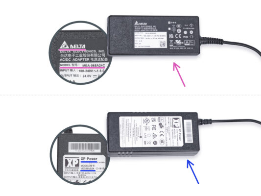
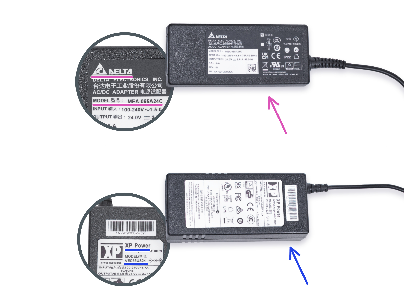
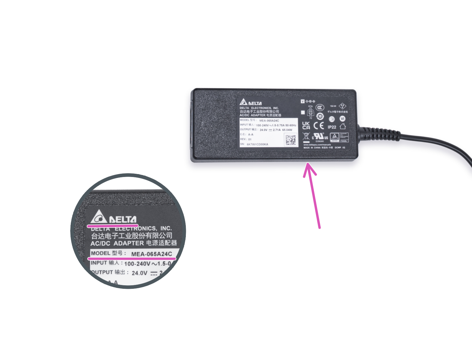
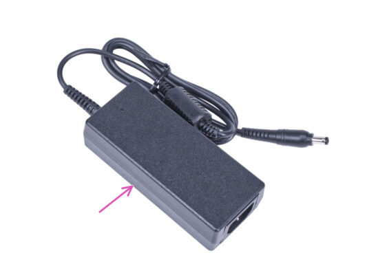
The White LED strip add-on has been shipped with two types of the external PSU, each from a different manufacturer. The functionality of both versions is the same, but the installation procedure is slightly different.
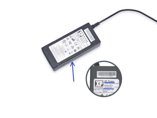
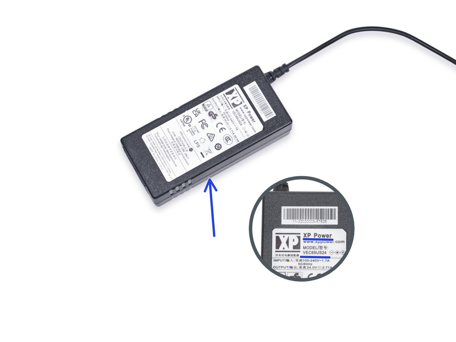
⬢On the label of the external PSU, check what model do you have and follow the appropriate instructions:
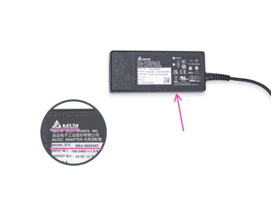
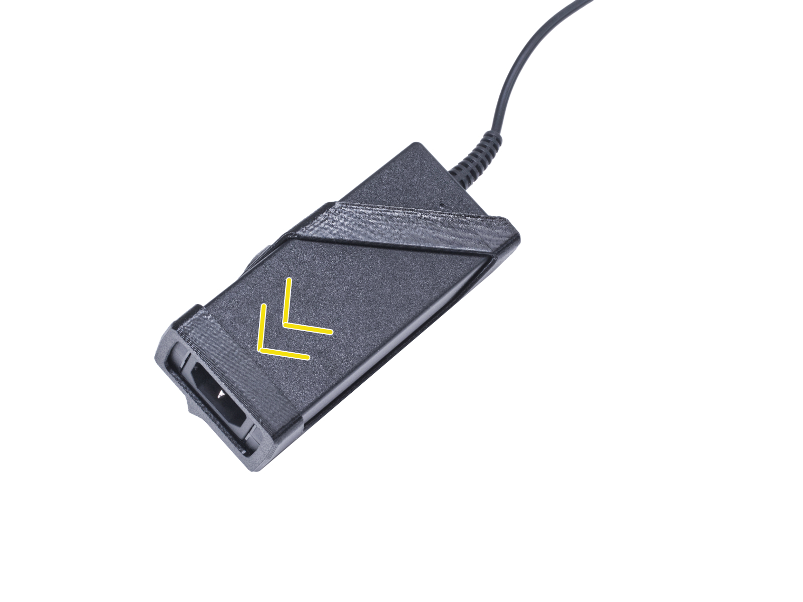
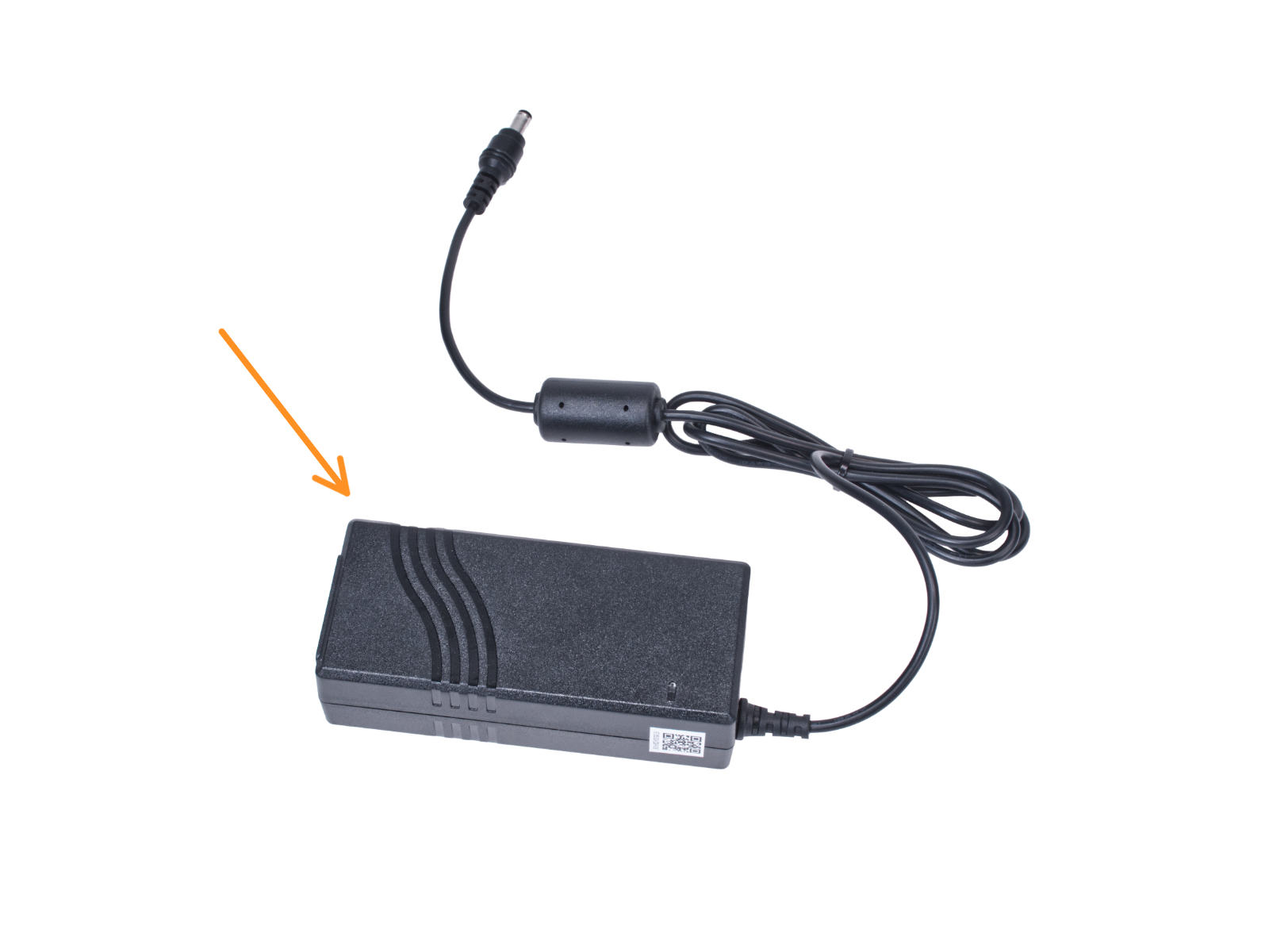
⬢The following instructions are intended for installing the White LED strip with the External PSU Delta model MEA-065A24C on the Original Prusa Enclosure.
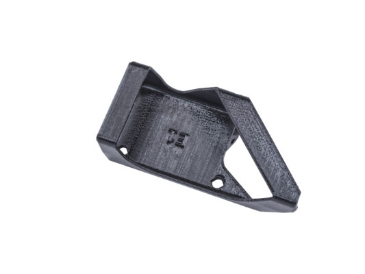
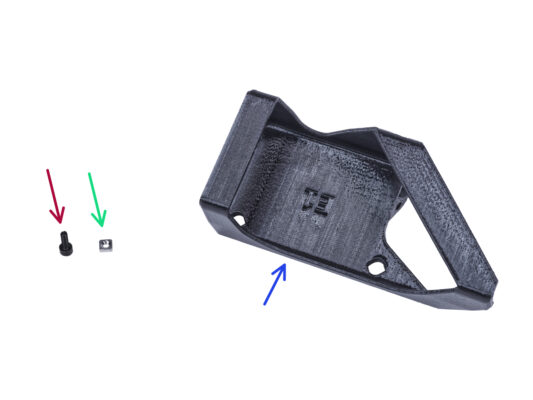
⬢Before you start installing the add-on, PRINT OUT ALL NECESSARY PLASTIC PARTS! The External-PSU-bracket-DELTA and the Basic-board-cover are available for download at Printables.com
Note: the External-PSU-bracket-DELTA is intended for mounting the external PSU to the enclosure. However, it is not necessarily required.
Note: the External-PSU-bracket-DELTA is intended for mounting the external PSU to the enclosure. However, it is not necessarily required. If you do not want to install the External PSU bracket, go to Preparing the printer.
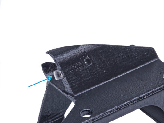
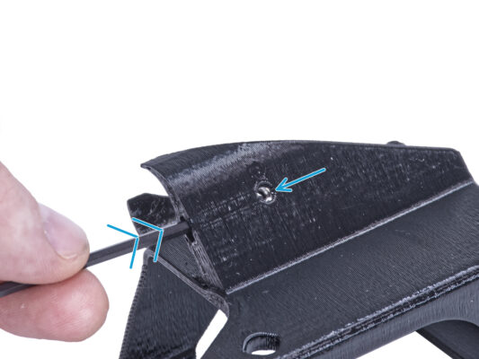
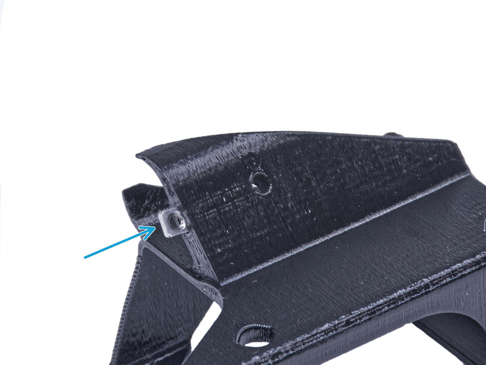
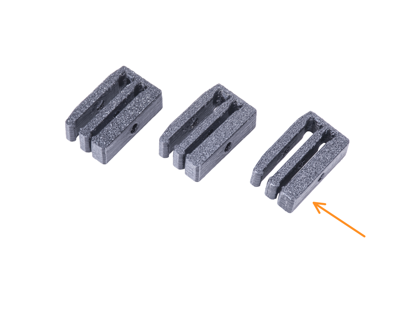
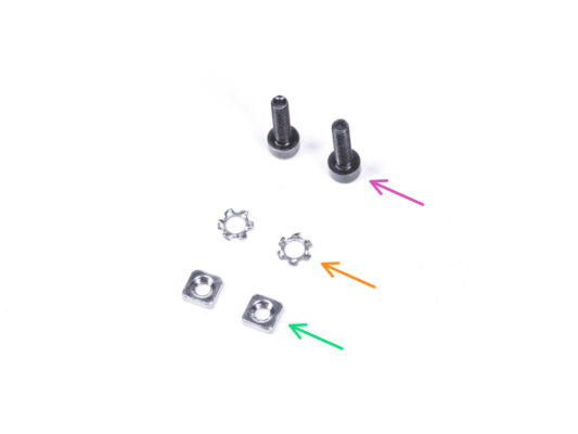
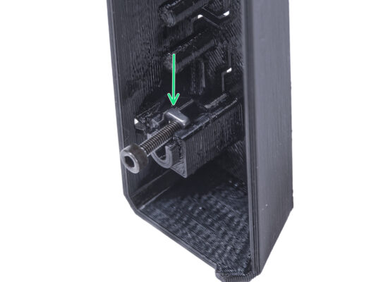
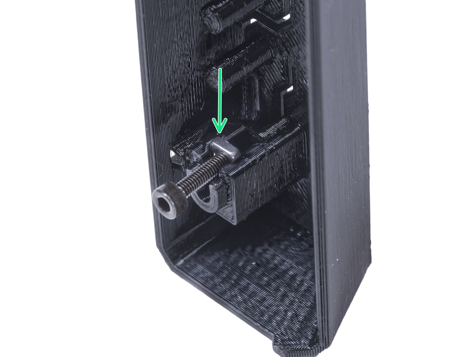
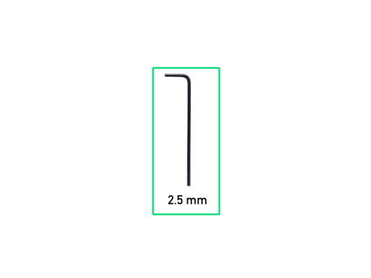
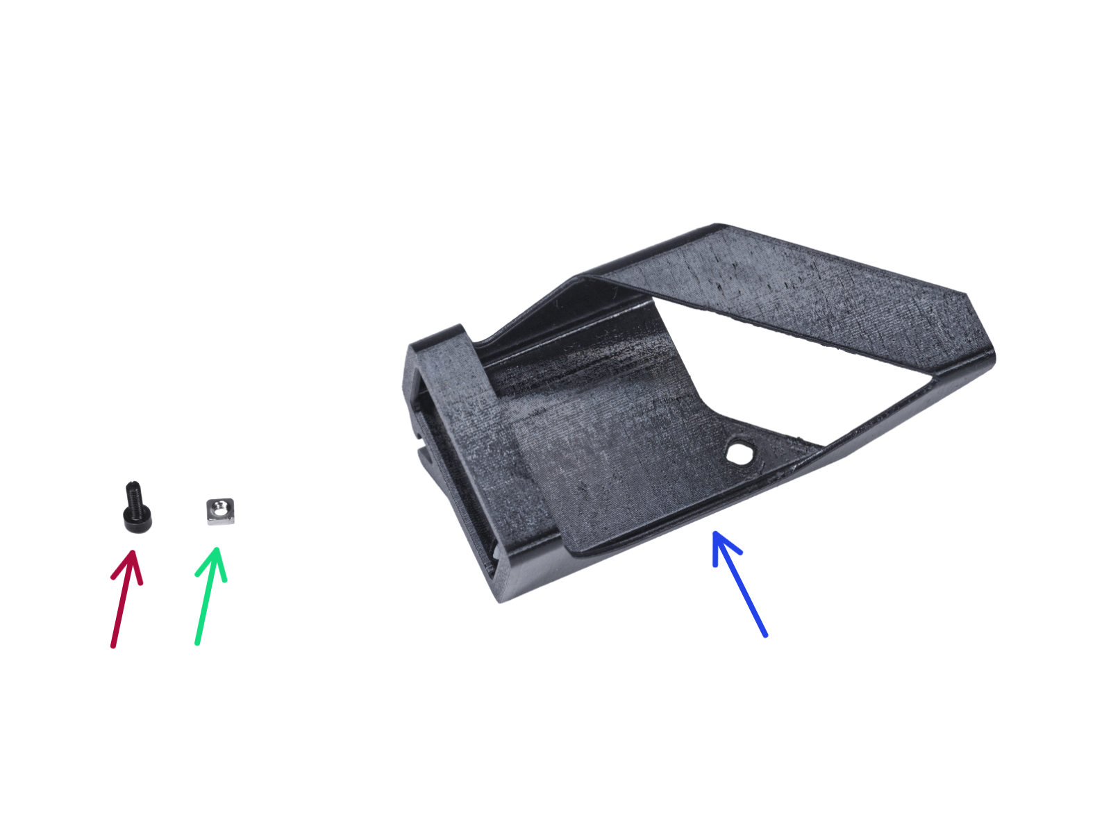
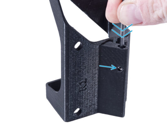
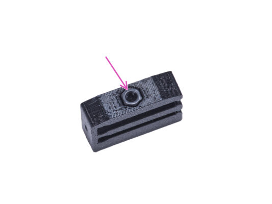
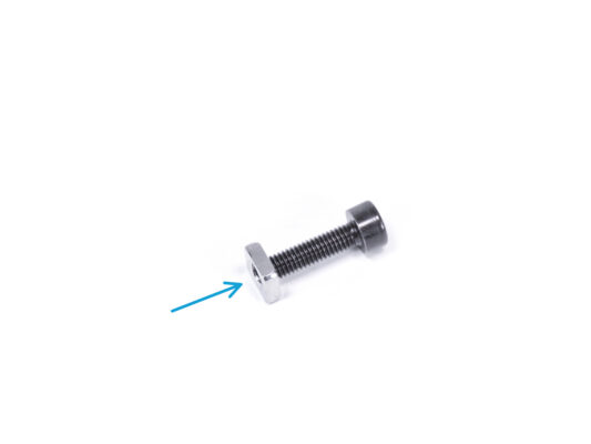
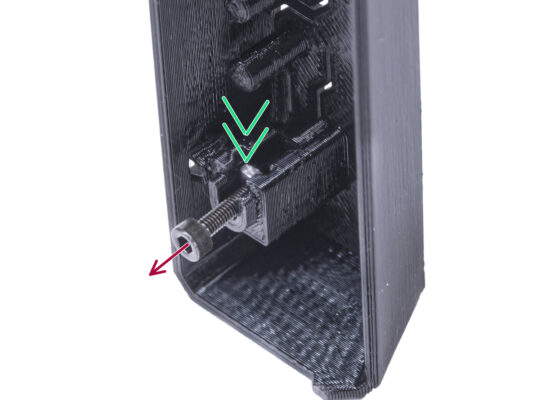
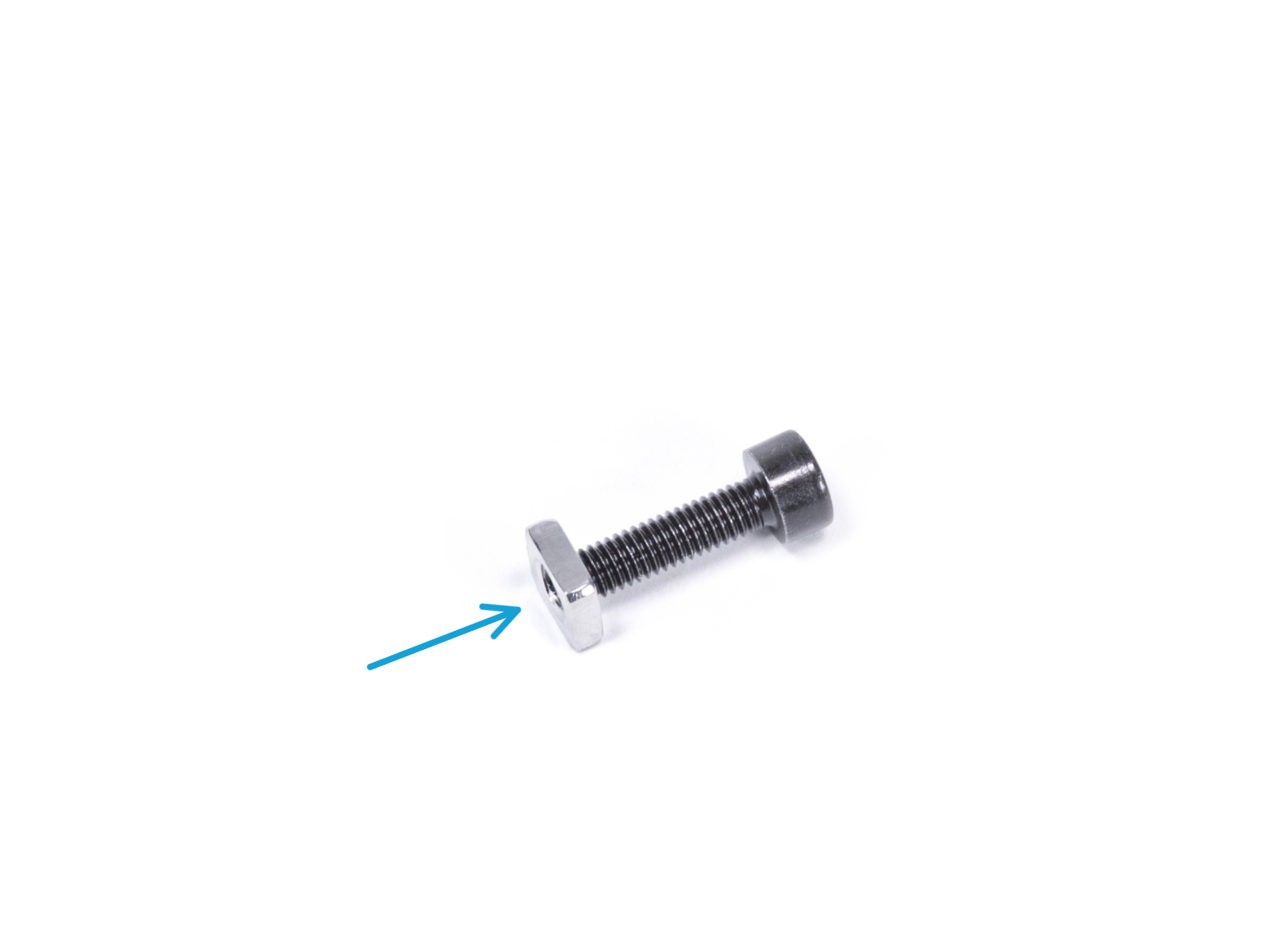
⬢Insert the M3nS nut into the External PSU bracket. Using the Allen key, push the nut all the way into the printed part and align the nut with the hole in the part.
⬢The following instructions are for mounting the external PSU to the enclosure. If you do not want to mount the external PSU to the enclosure, go to Installing the PSU.
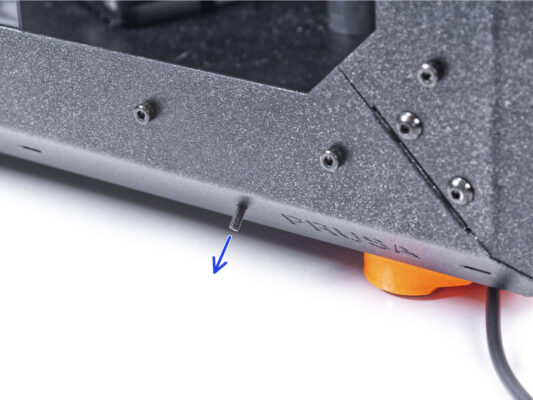
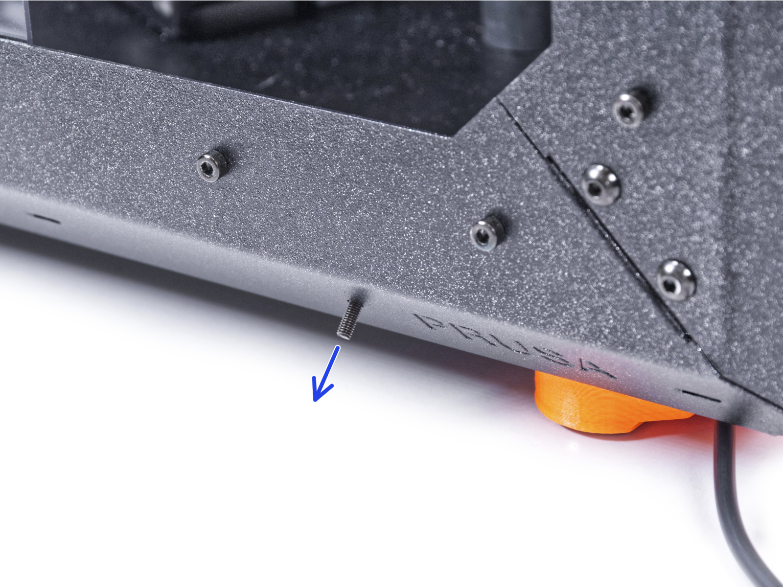
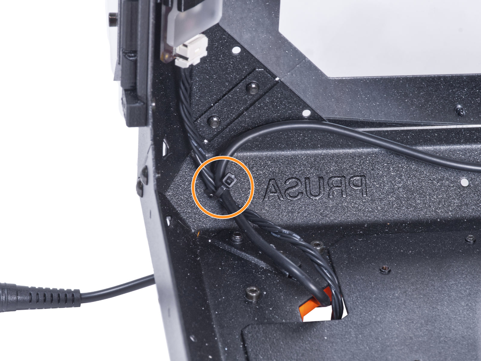
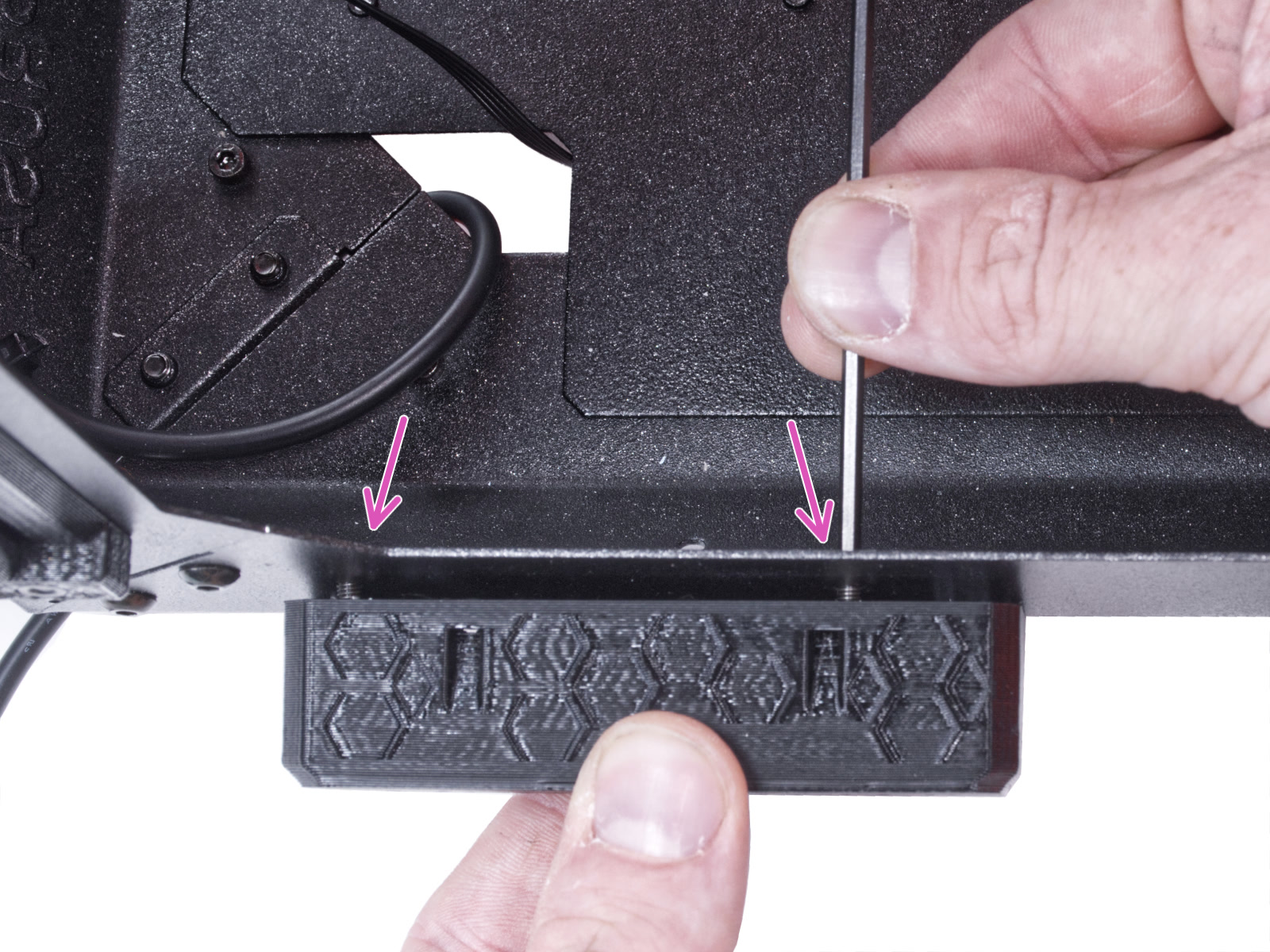
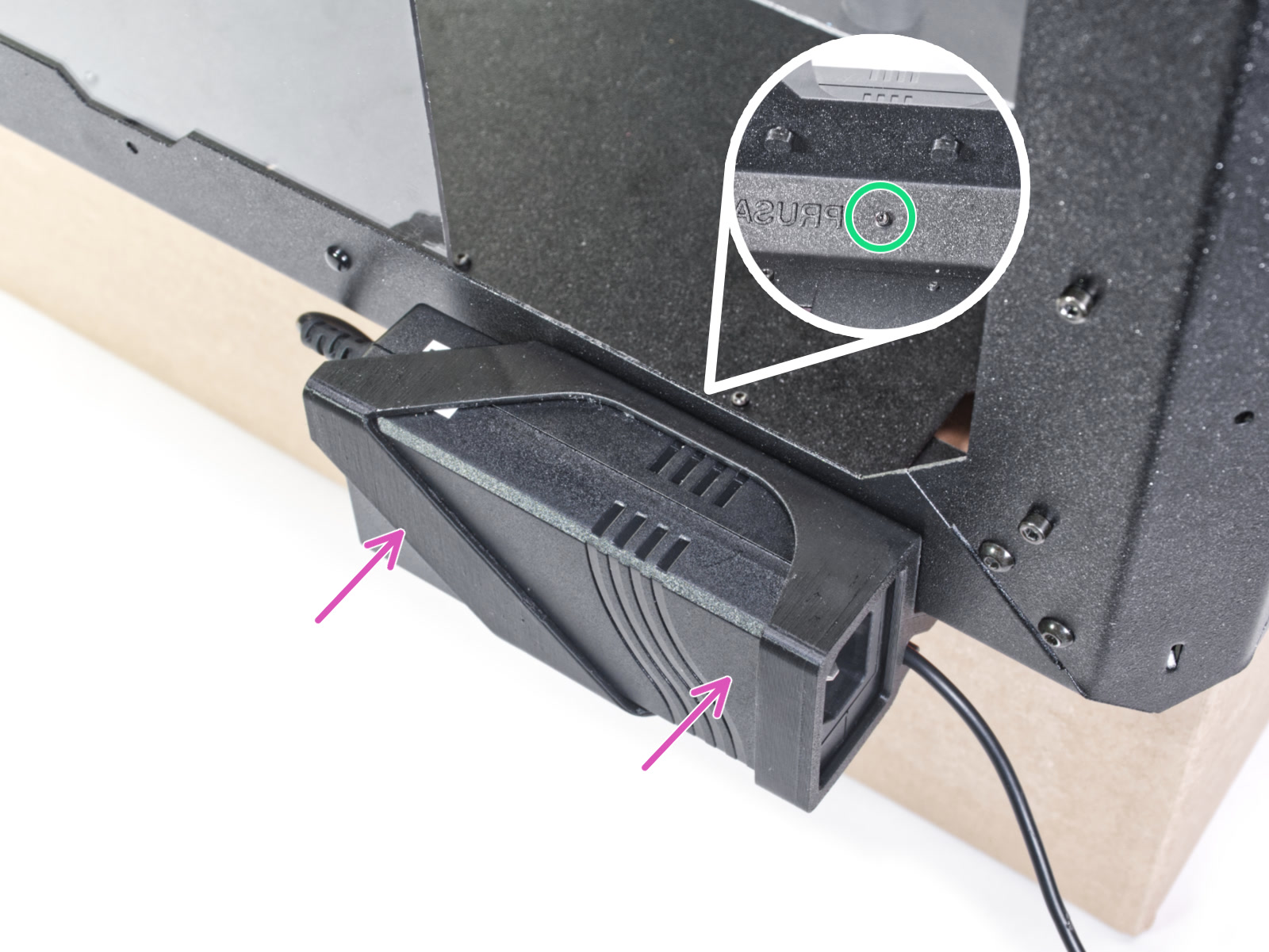
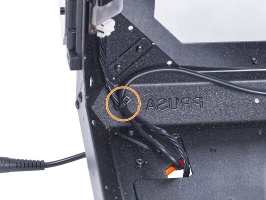
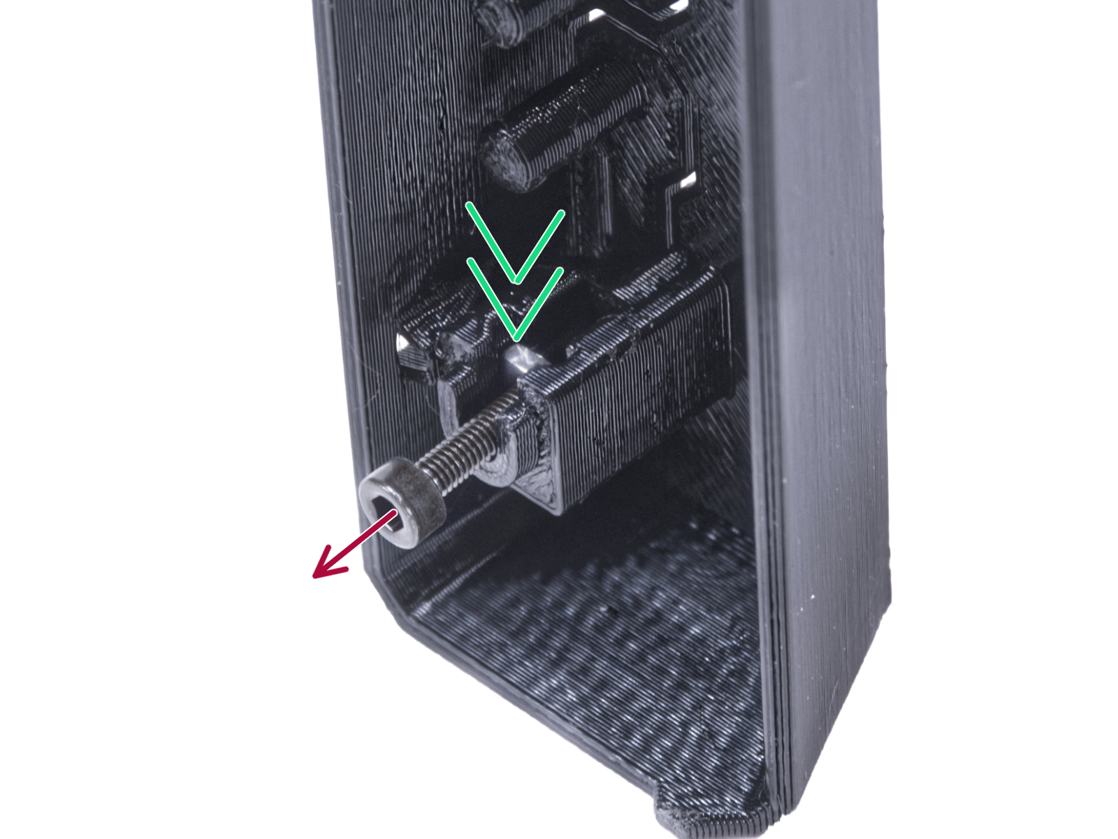
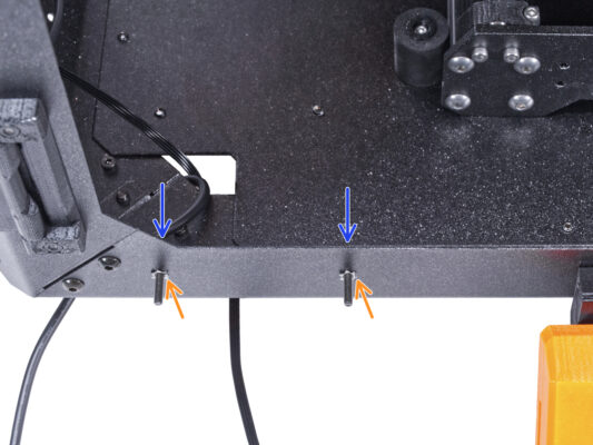
⬢From the inside, push the M3x8 screw through the hole in the bottom profile next to the PRUSA logo.
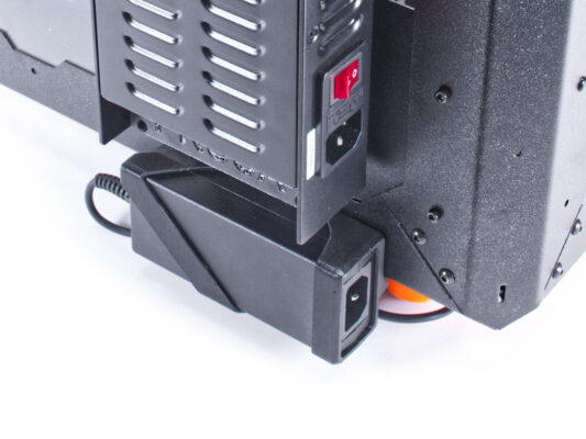
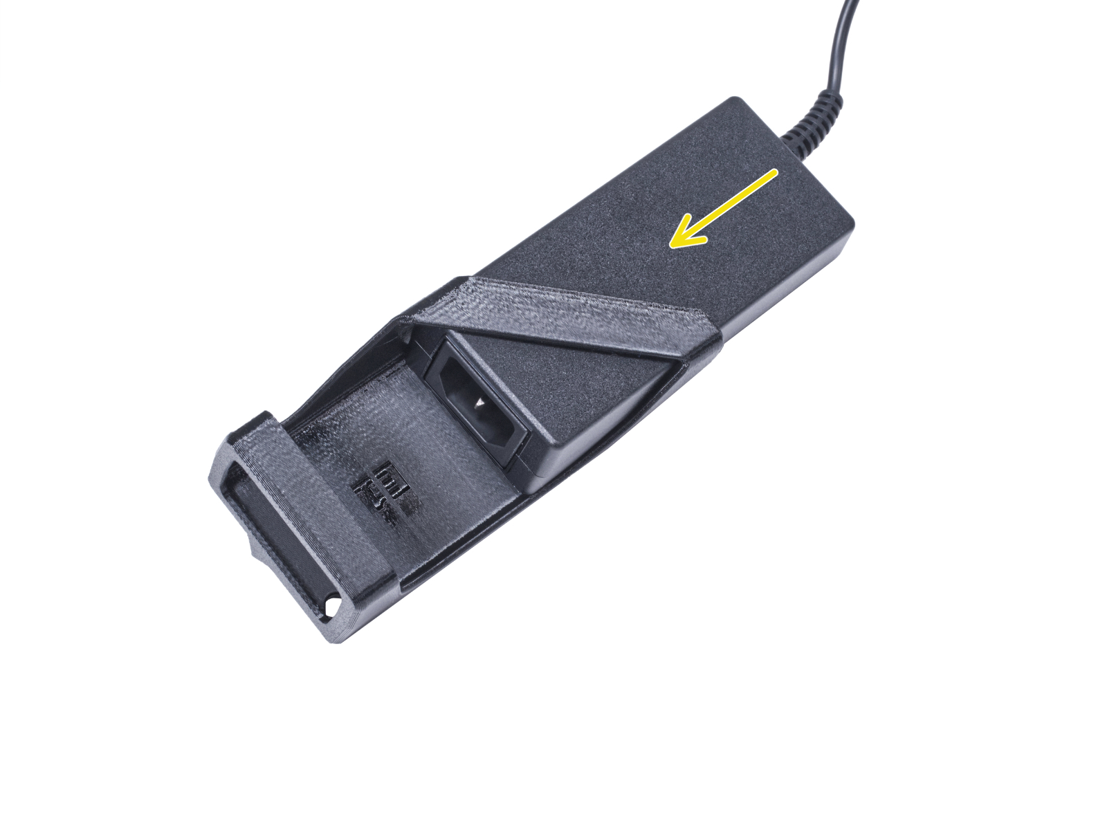
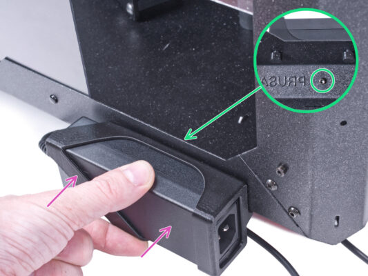
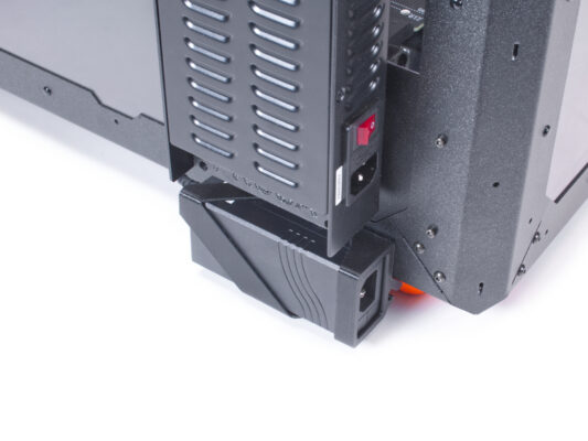
⬢Attach the external PSU assembly on profile. And align it against the screw.
⬢Tighten the M3x8 screw from inside to mount the external PSU.
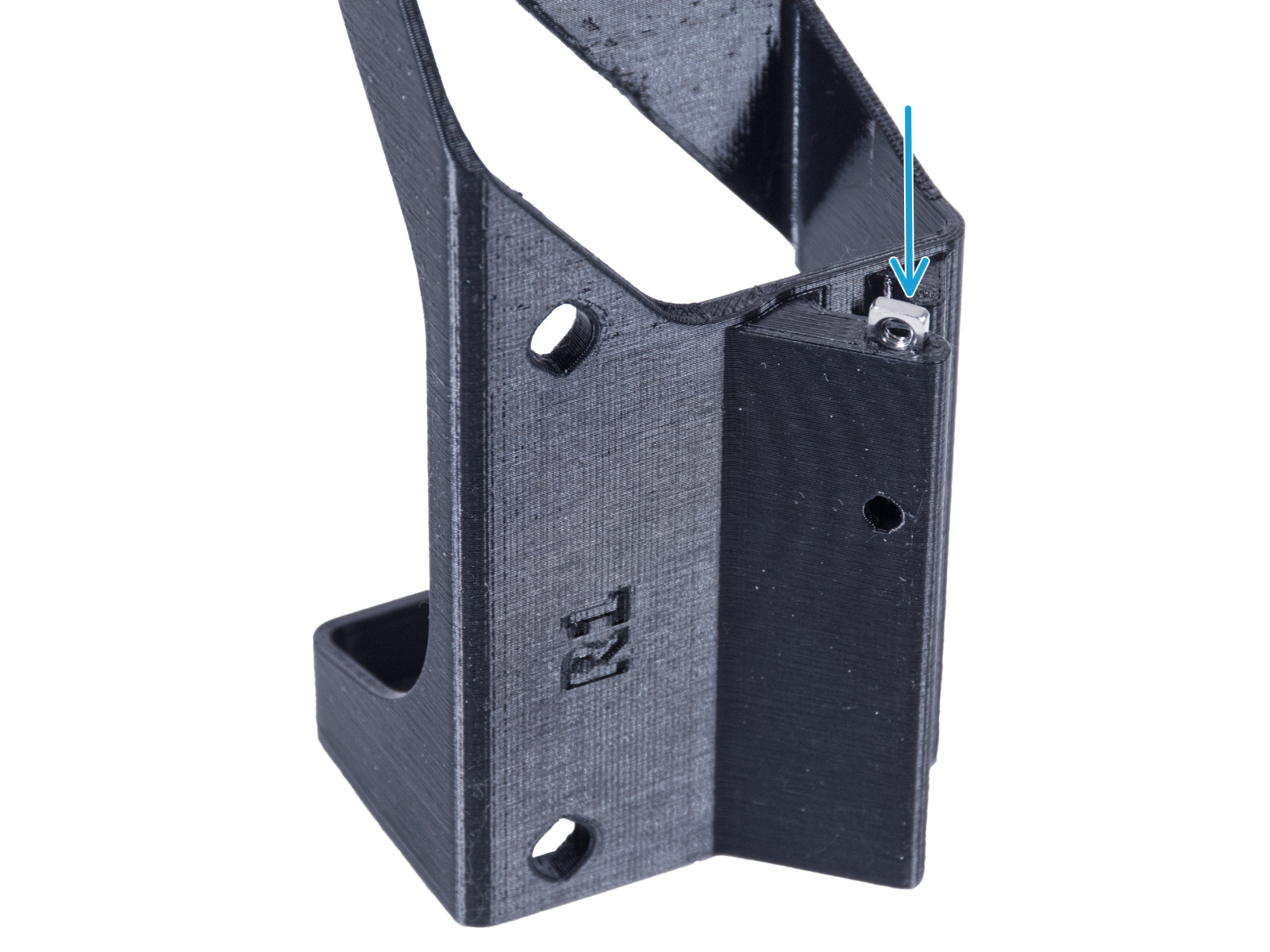
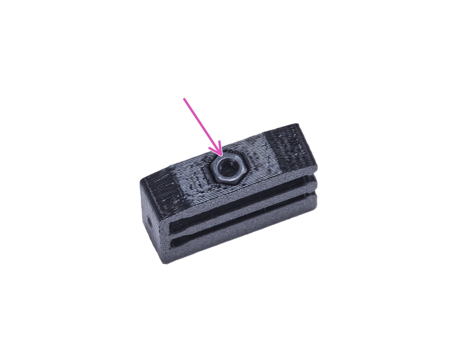
The nut must be completely embedded in the printed part and flush with the surface of the part. Insufficient embedment of the nut can cause problems when mounting in the enclosure.
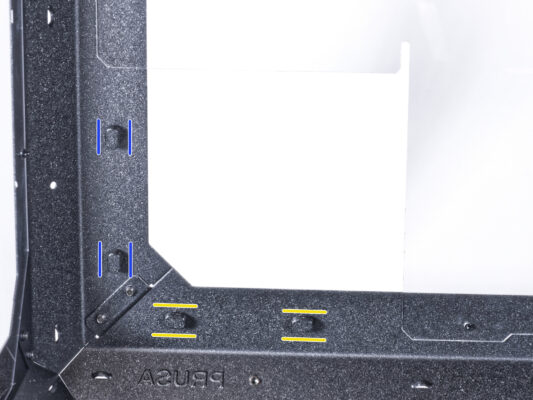
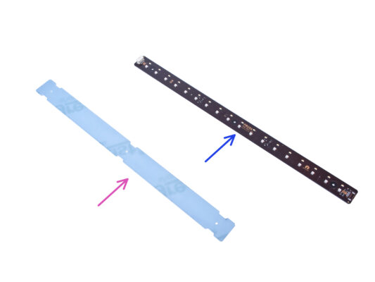
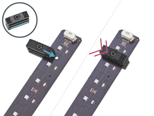
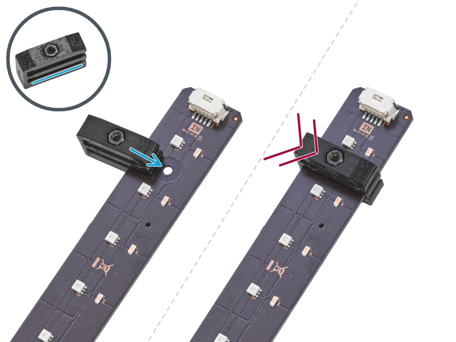
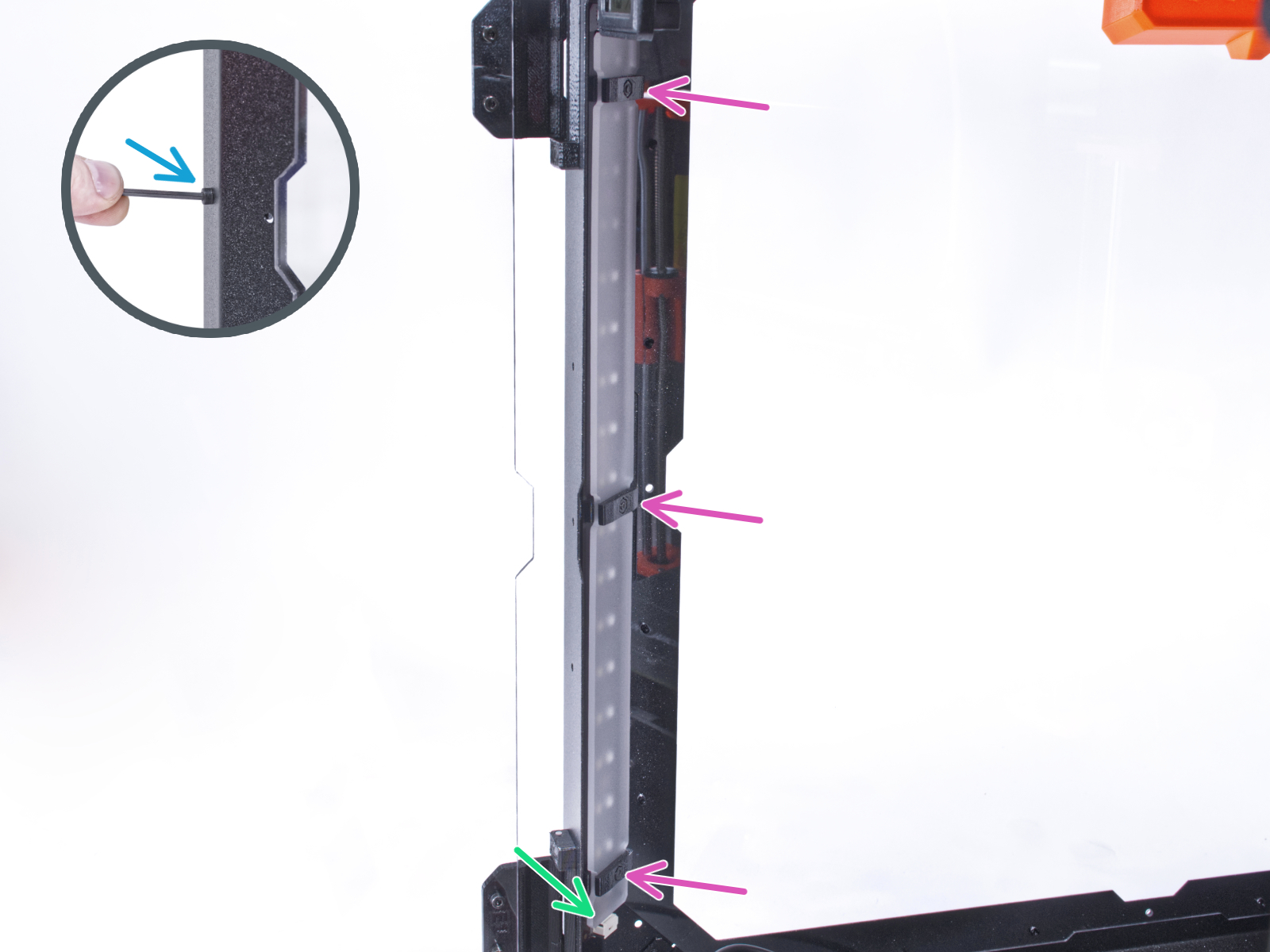
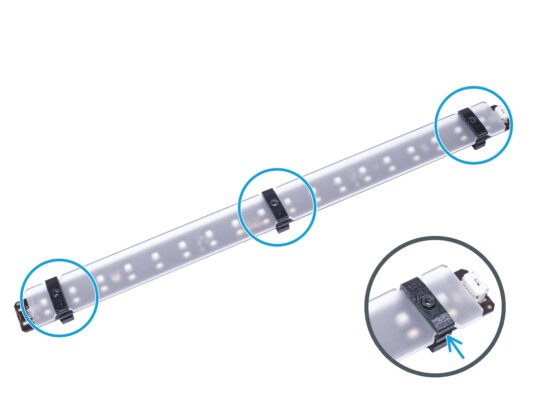
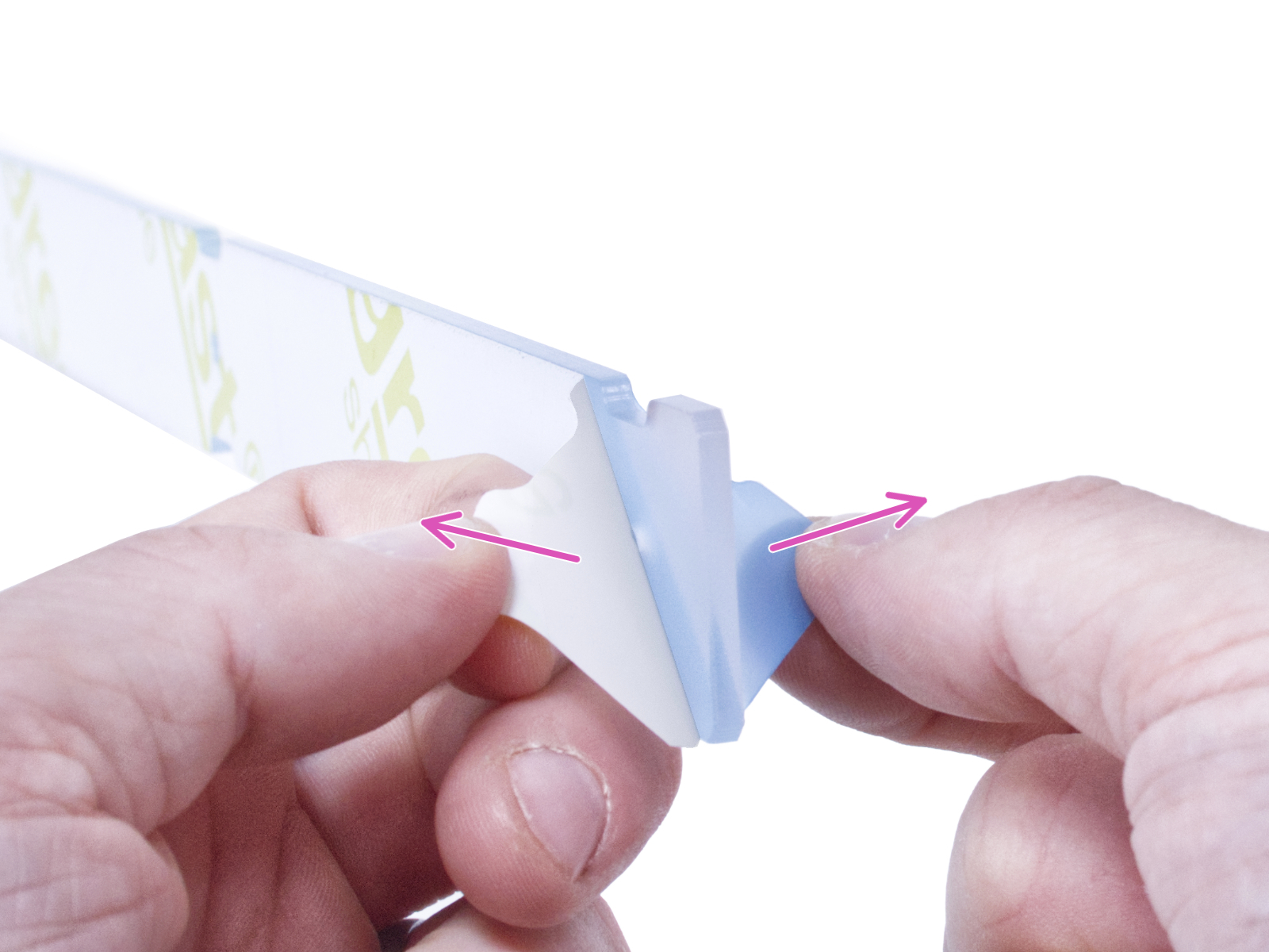
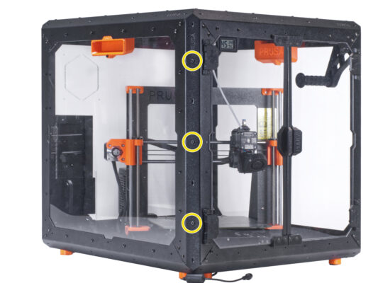
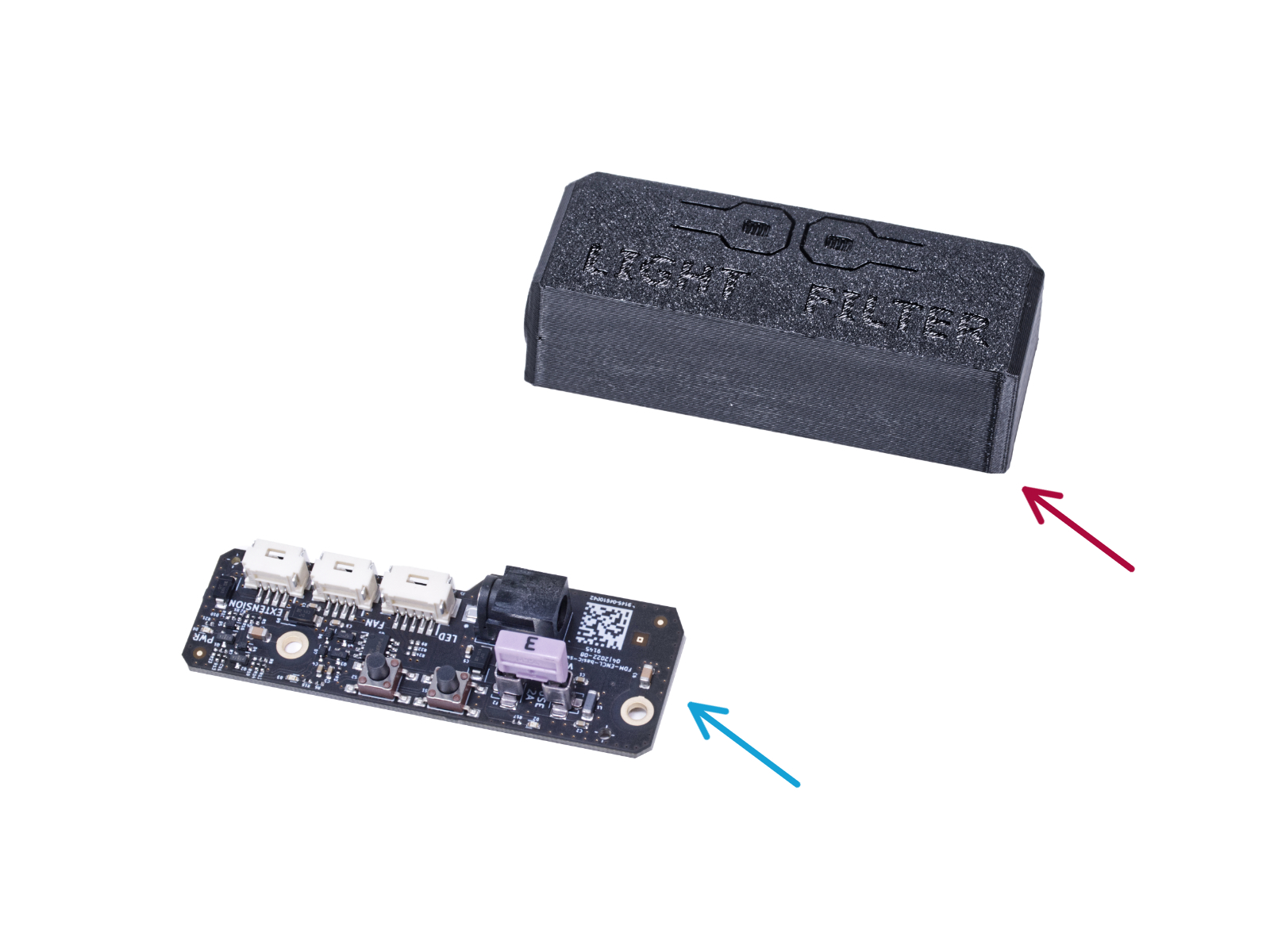
⬢Slide the lower slot of the LED Stick Bracket on the LED Stick Board and align the bracket against the first hole in the LED Stick Board closest to the (white) LED stick connector.
Avoid sliding the bracket over chips and diodes! It can be fatally damaged.
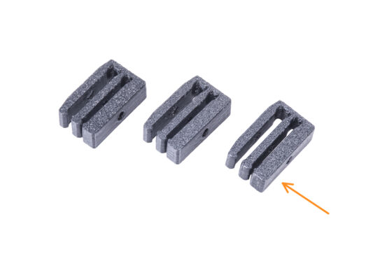
⬢Push the LED Stick Bracket all the way on the LED Stick Board.
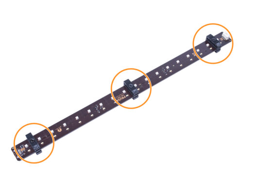
⬢Use this procedure for all three LED Stick Brackets.
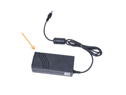
⬢The following instructions are intended for installing the White LED strip with the External PSU XP Power model VEC65US24 on the Original Prusa Enclosure.
⬢Before you start installing the add-on, PRINT OUT ALL NECESSARY PLASTIC PARTS! The External-PSU-bracket-XP and the Basic-board-cover are available for download at Printables.com
Note: the External-PSU-bracket-XP is intended for mounting the external PSU to the enclosure. However, it is not necessarily required.
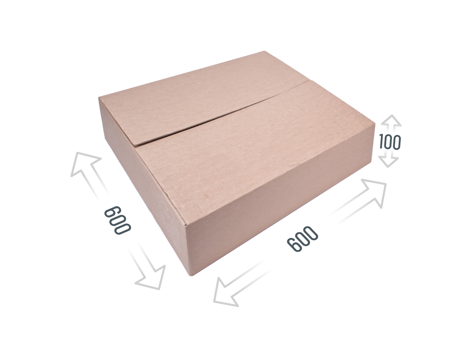
⬢In the following steps, you will need to access the bottom of the enclosure. You achieve this by having one of the bottom edges of the frame extend beyond the work surface. It is recommended to use a cardboard box and put the enclosure on it.
⬢The size of the box must be at least 600 x 600 x 100 mm.
Hint: you can use the original cardboard box of the Enclosure packaging.
Do not place the enclosure on the box now. Wait for the instruction.
Note: the External-PSU-bracket-XP is intended for mounting the external PSU to the enclosure. However, it is not necessarily required. If you do not want to install the External PSU bracket, go to Removing the LCD.
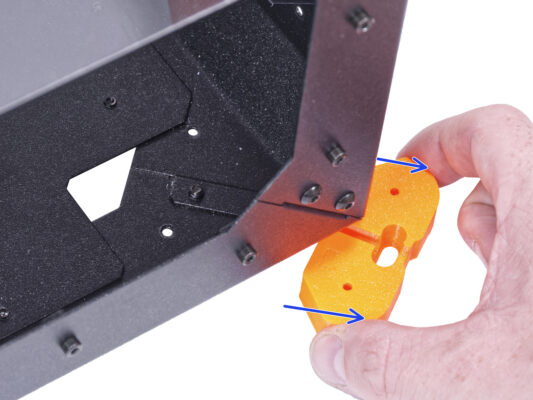
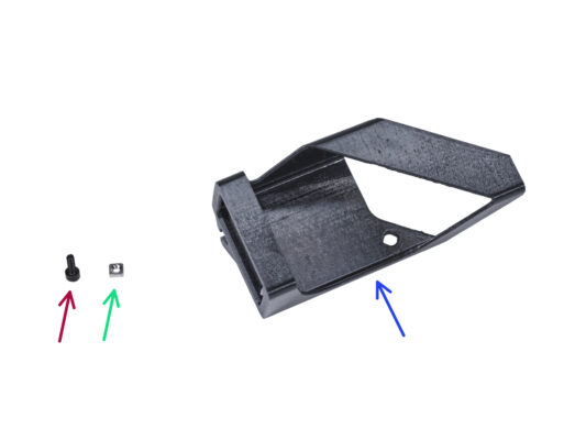
⬢Insert the M3nS nut into the External-PSU-bracket-XP. Using the Allen key, push the nut all the way into the printed part and align the nut with the hole in the part.
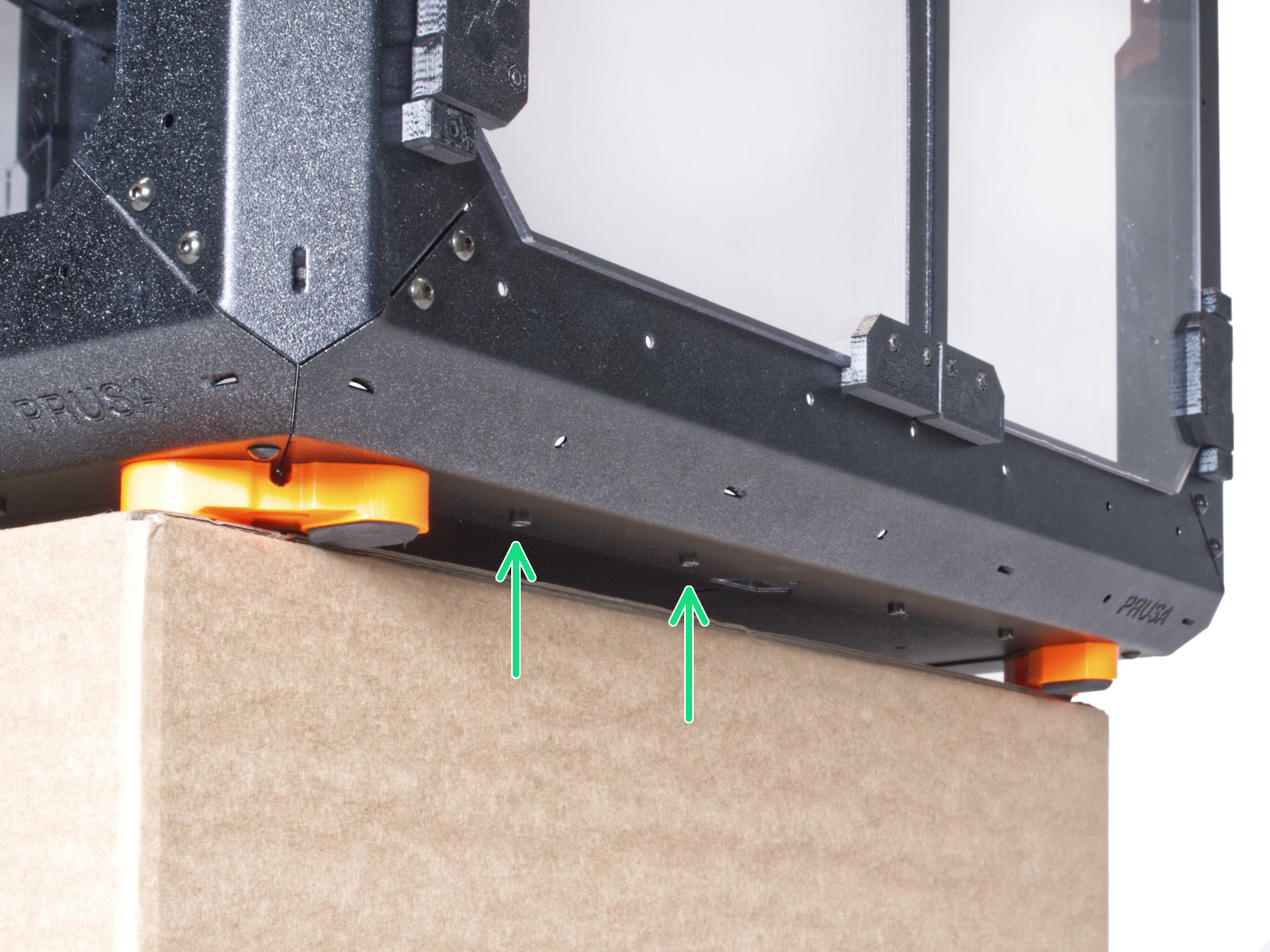
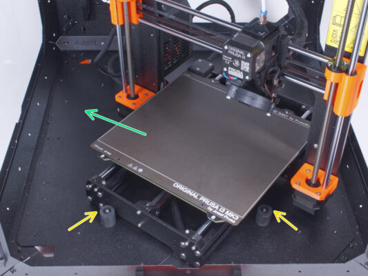
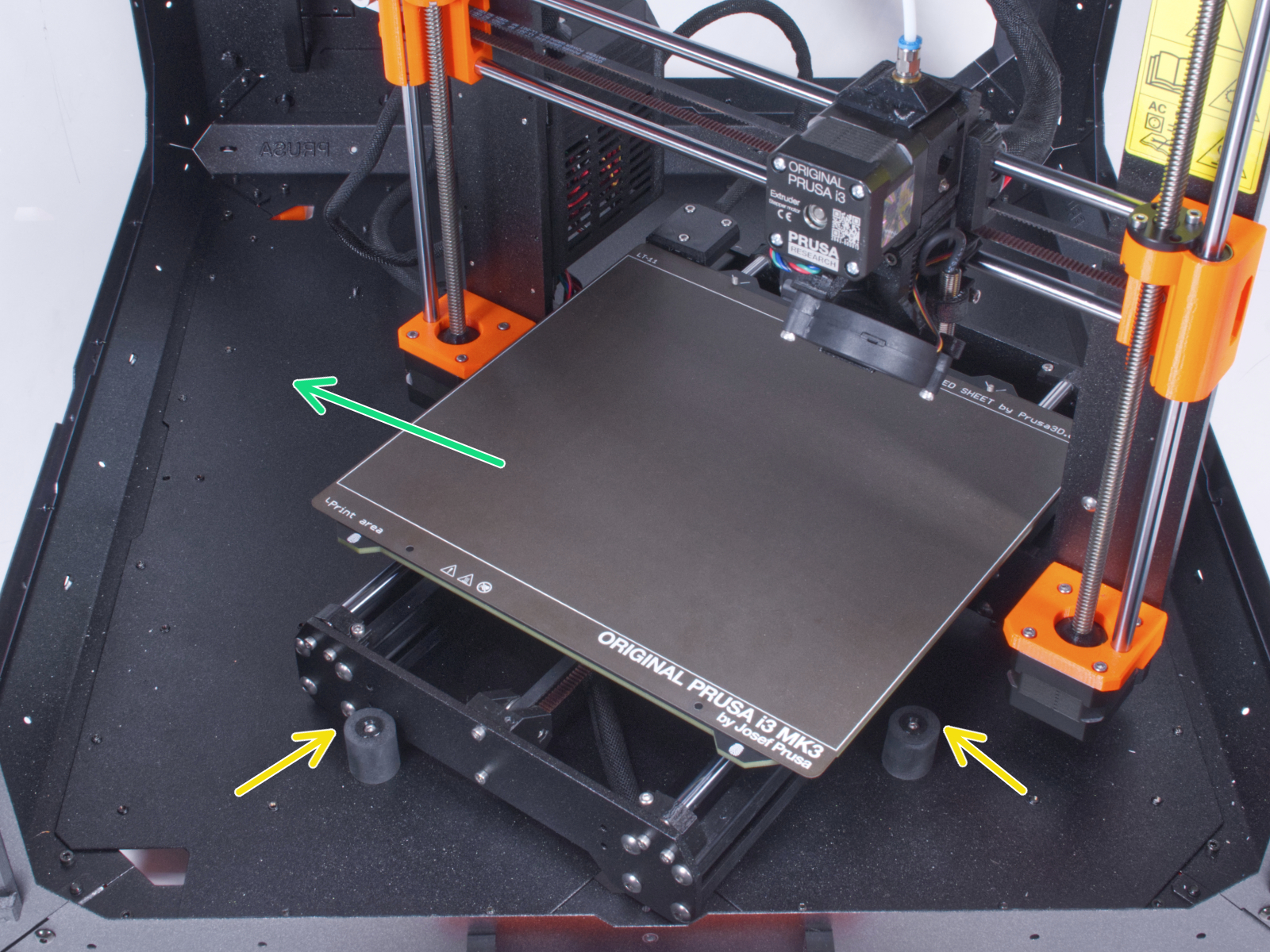
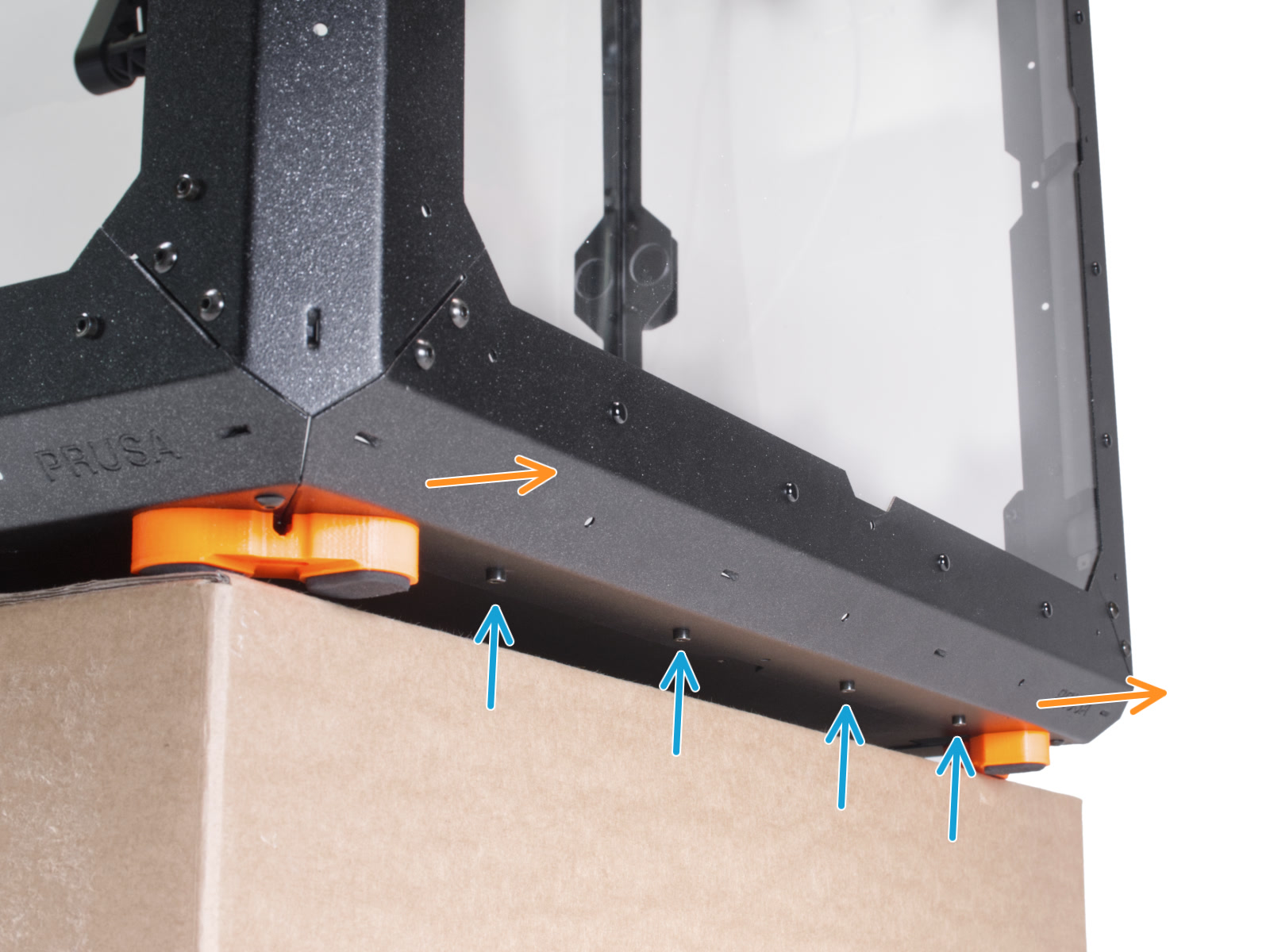
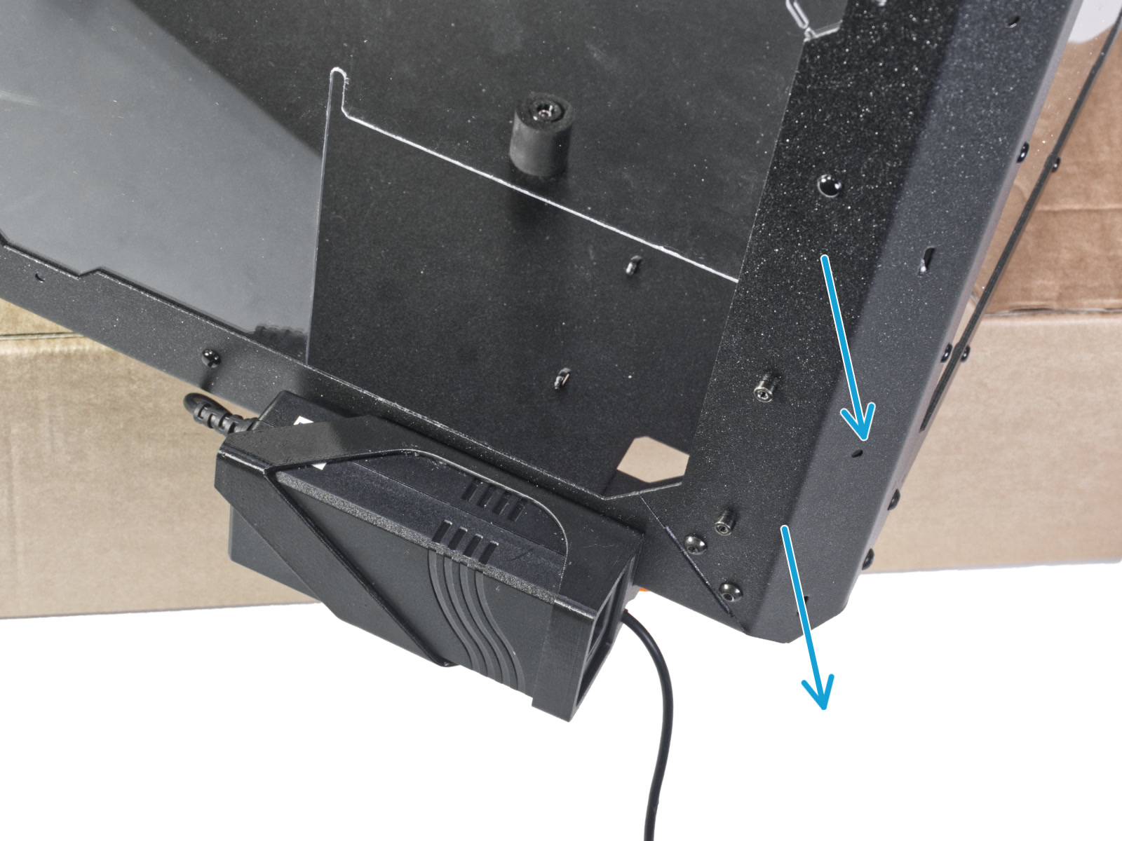
⬢Place the enclosure on the cardboard box with the rear side (side with the PSU hole in the back panel) overhanging the box.
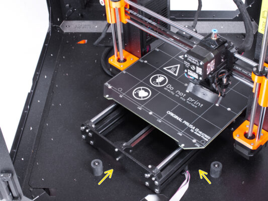
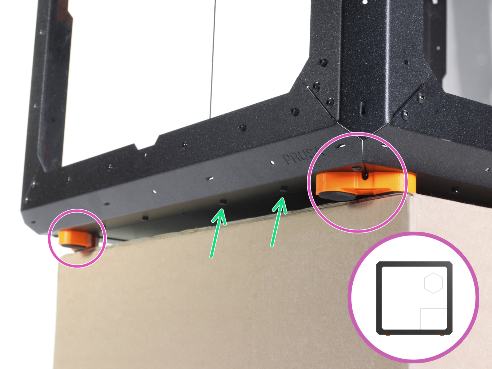
⬢It is necessary that both feet on the left side stand on one anti-vibration pad. See the detail. Avoid placing the enclosure directly on the frame.
WARNING: Be extra careful and make sure the enclosure is stable and doesn't wobble. Otherwise, the enclosure may fall off the box and hurt you and damage.
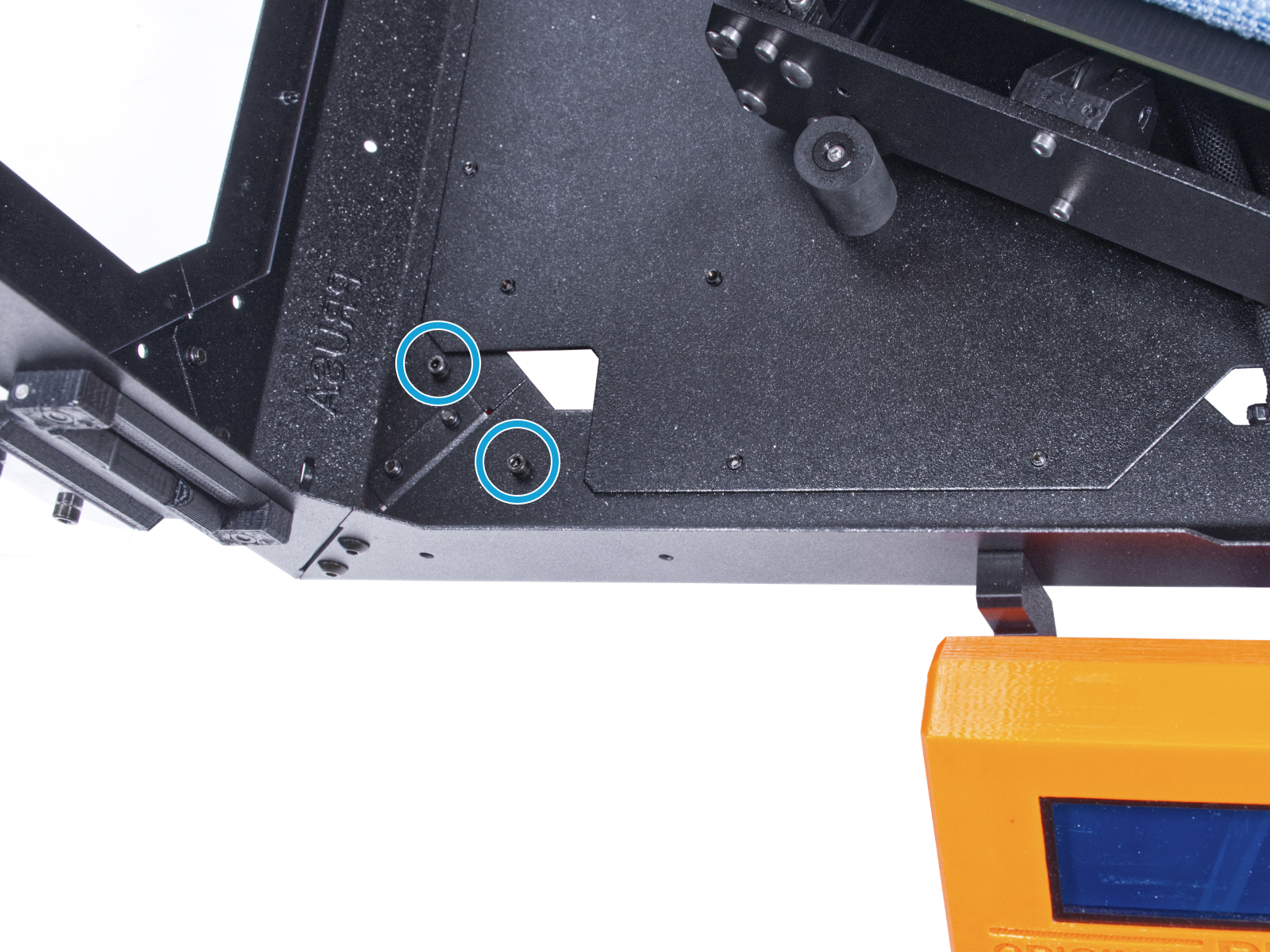
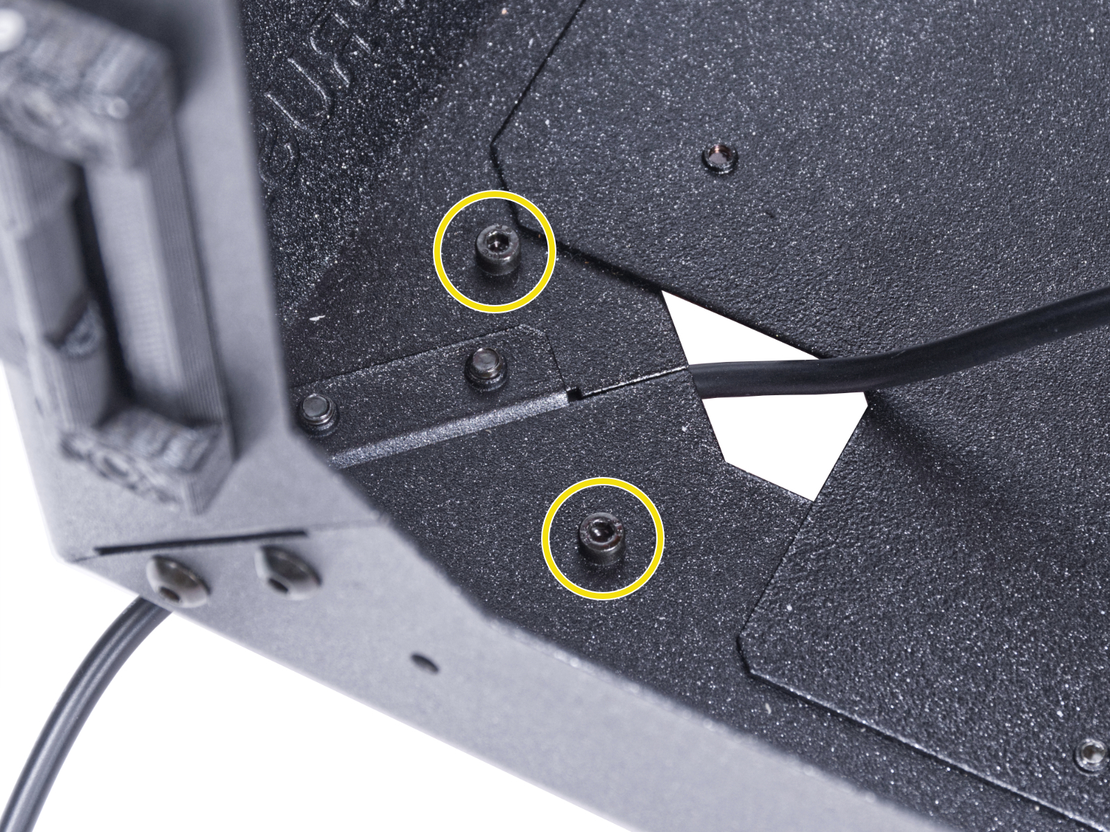
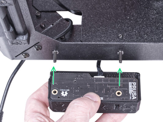
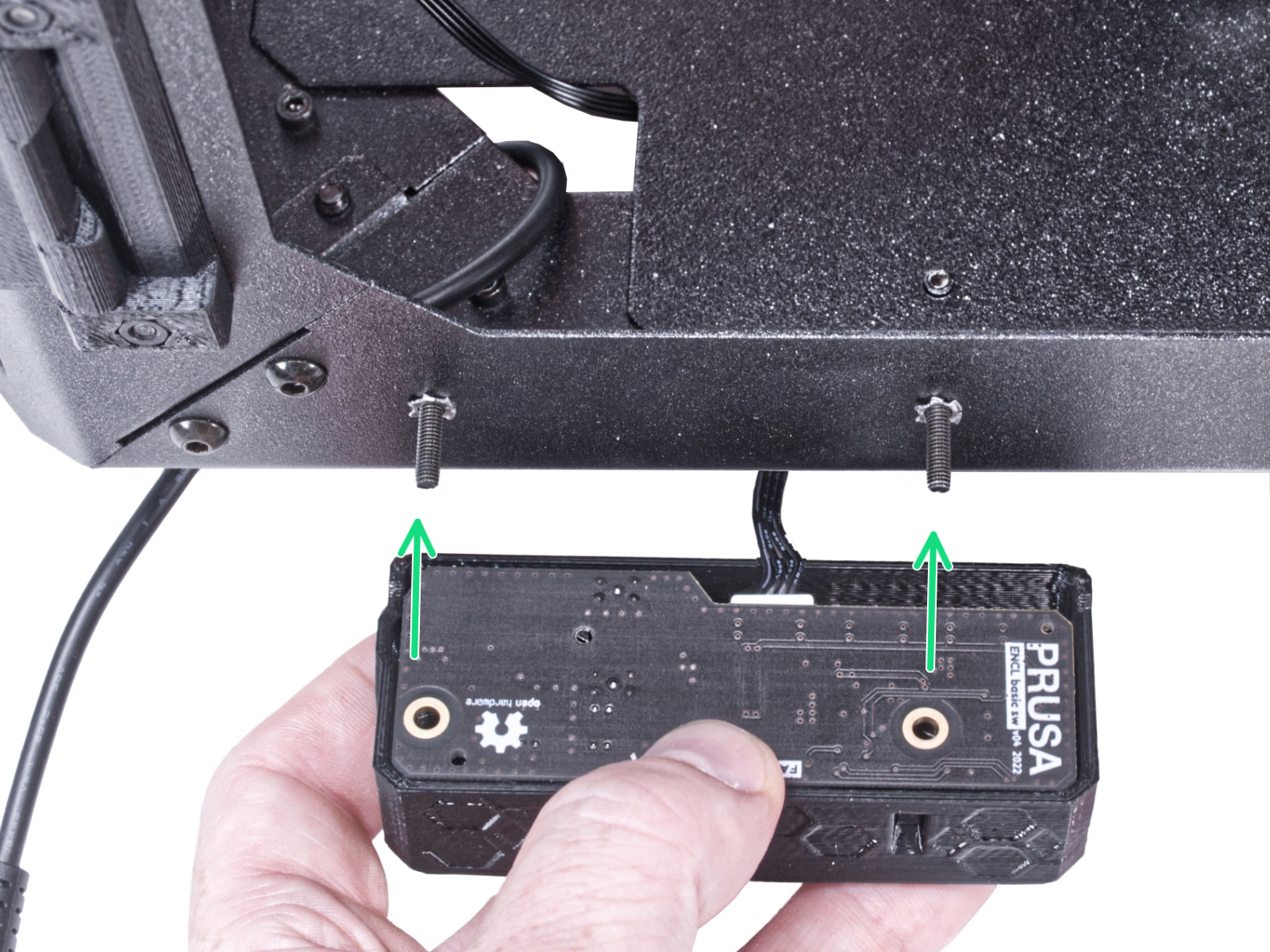
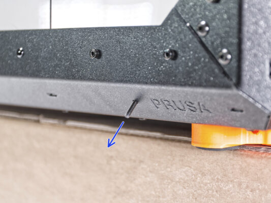
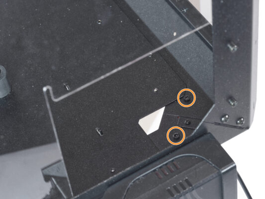
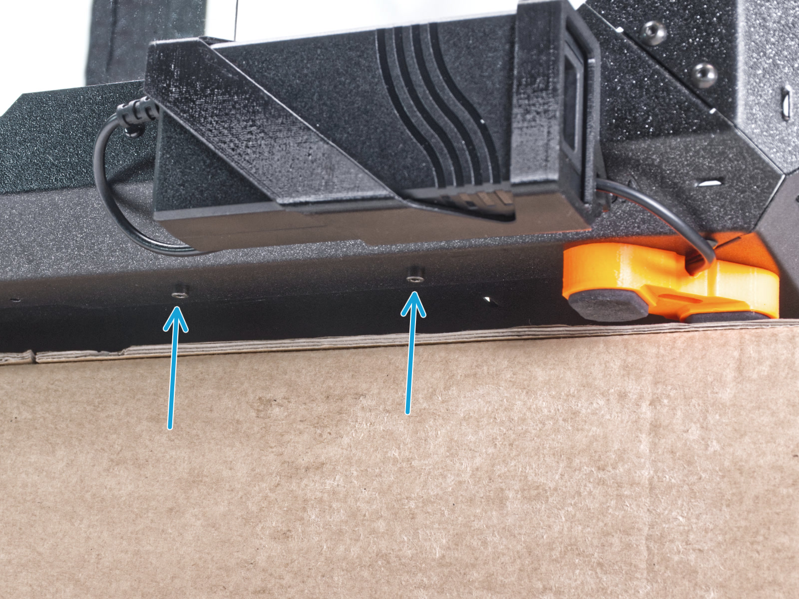
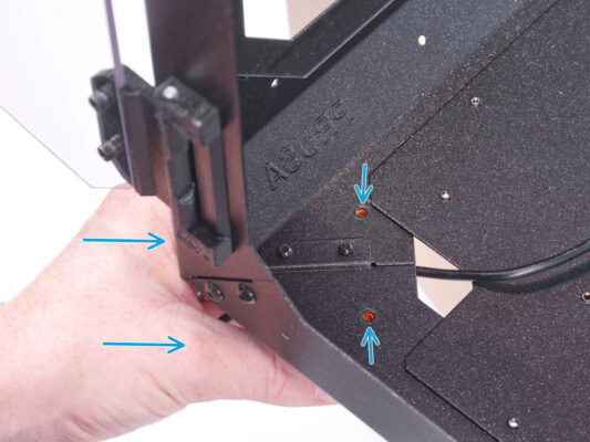
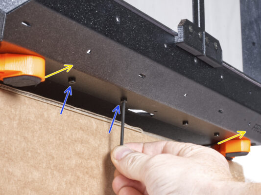
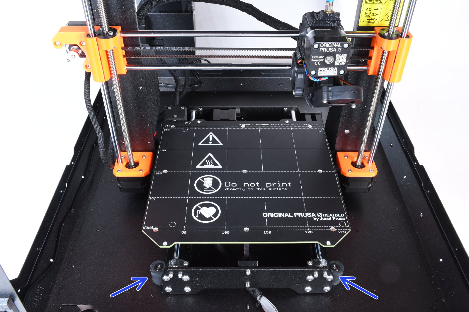
⬢From the bottom, release and remove two screws nearest the right corner.
⬢In the same way, move the enclosure so that the right side overhangs the box.
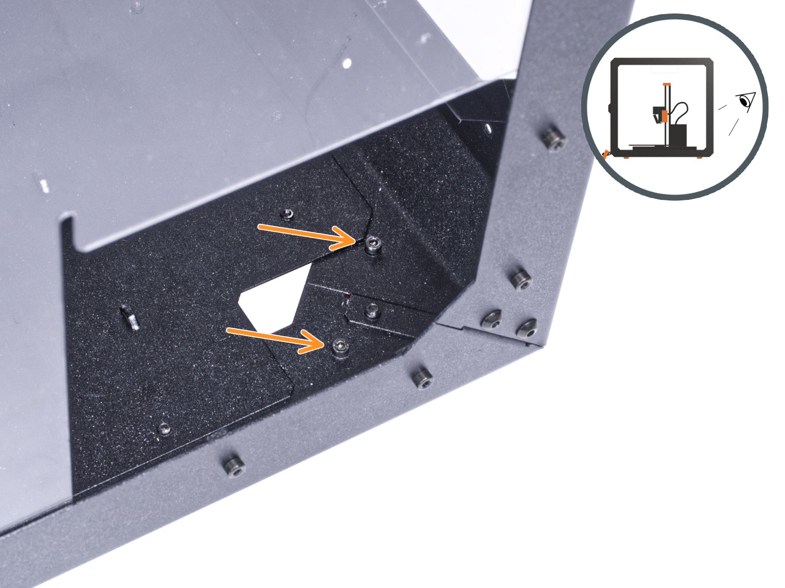
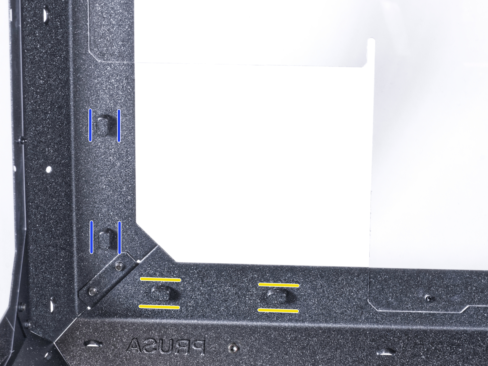
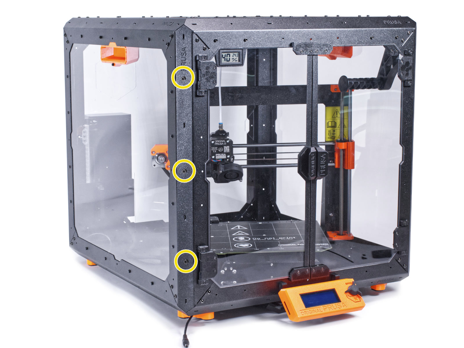
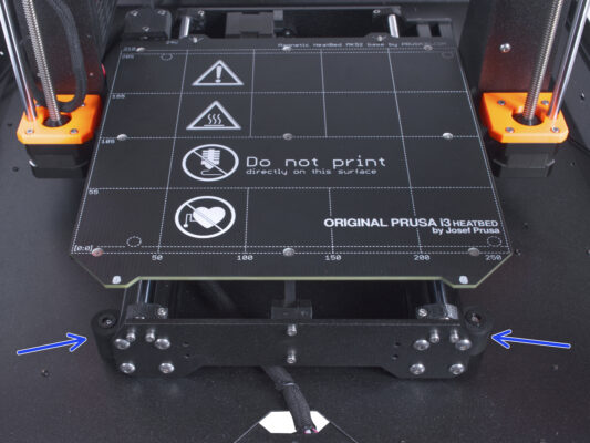
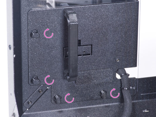
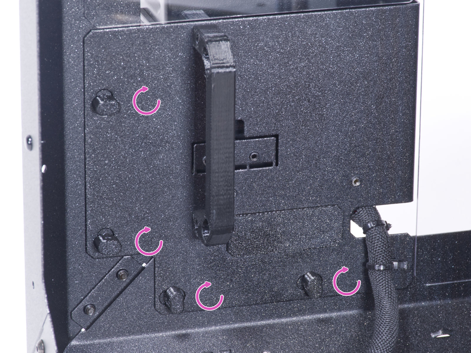
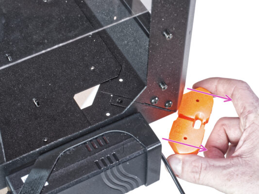
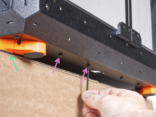
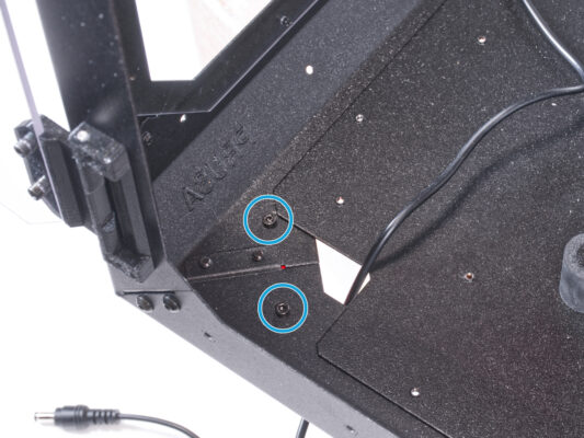
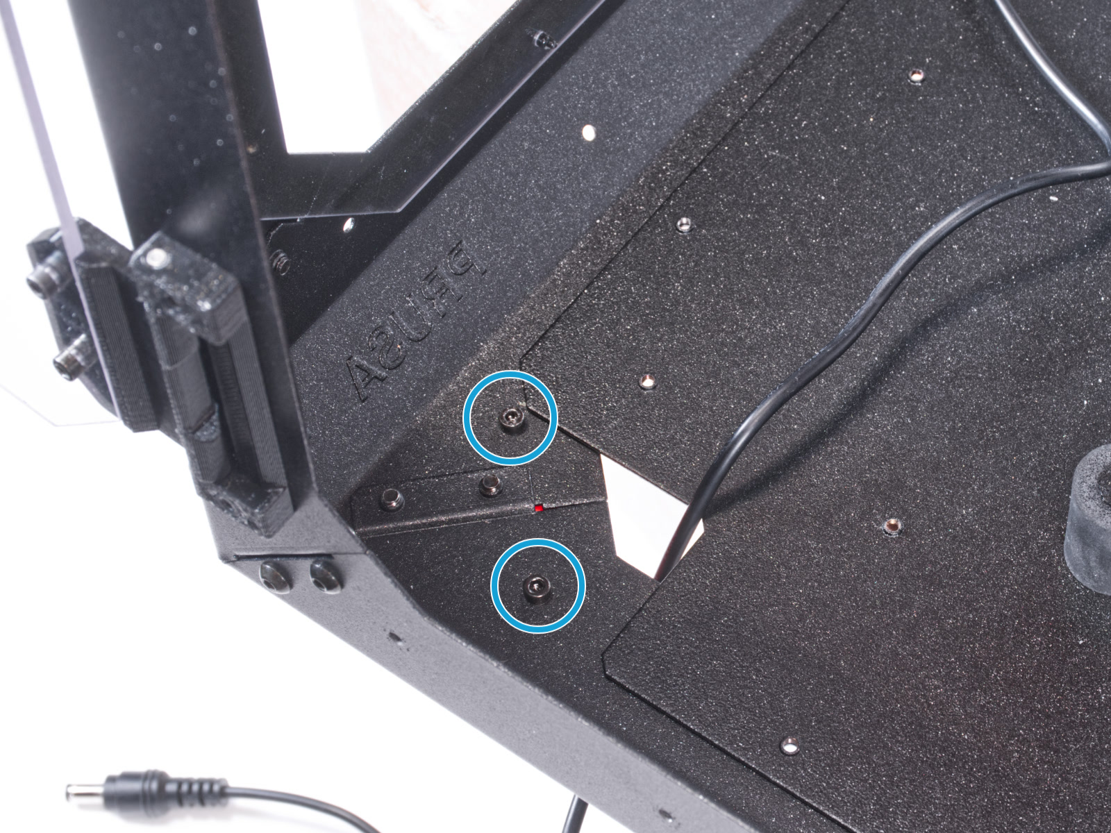
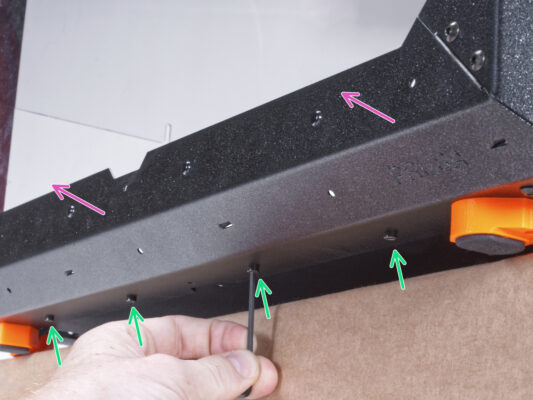
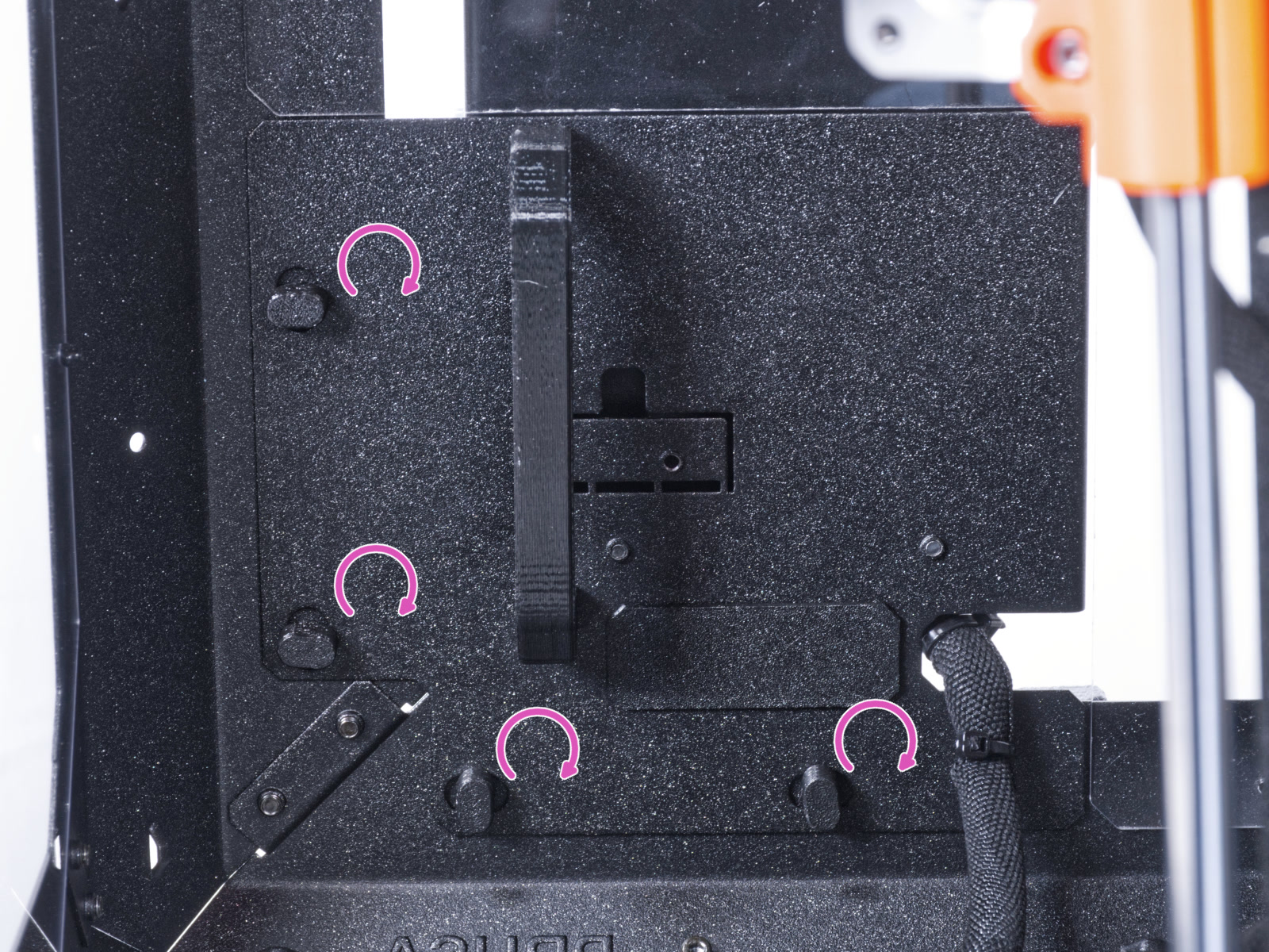
⬢Release and remove four screws from the bottom profile.
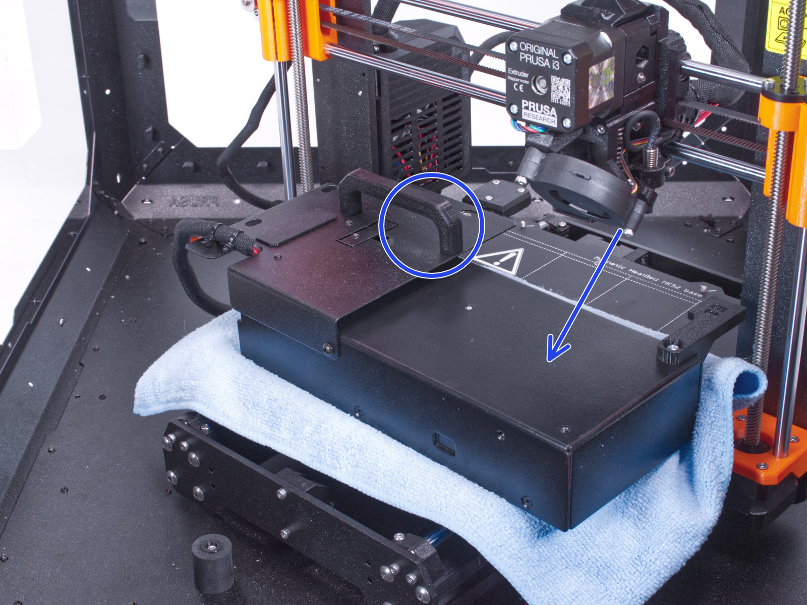
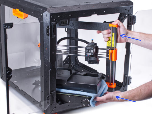
⬢Place the enclosure so that all feet are on the surface.
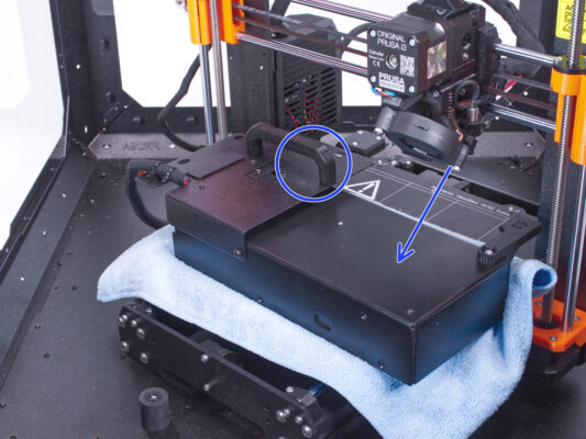
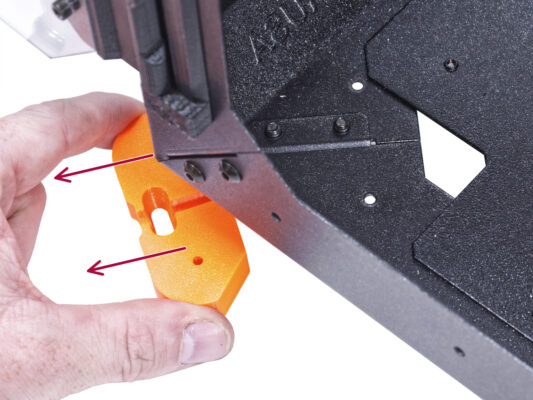
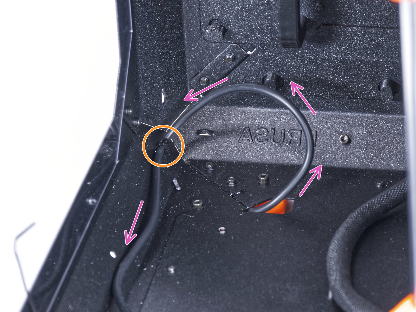
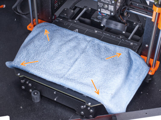
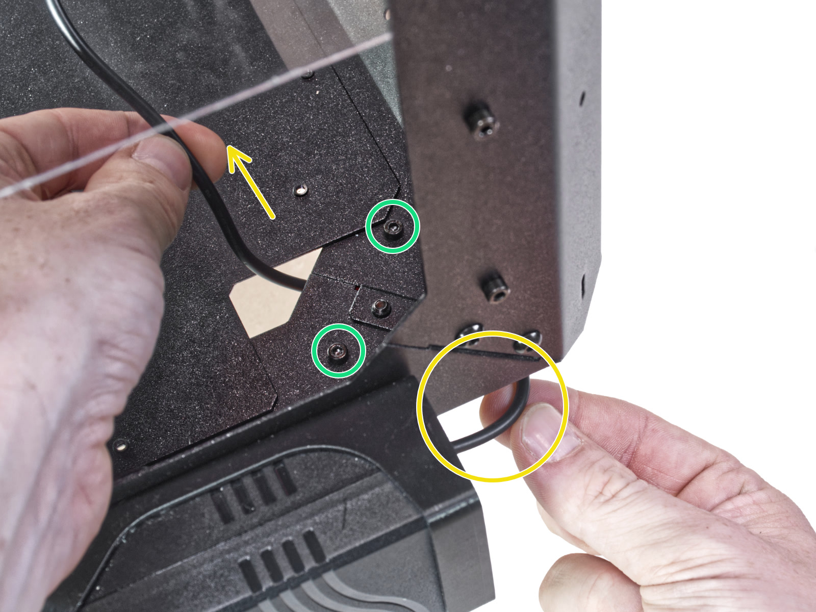
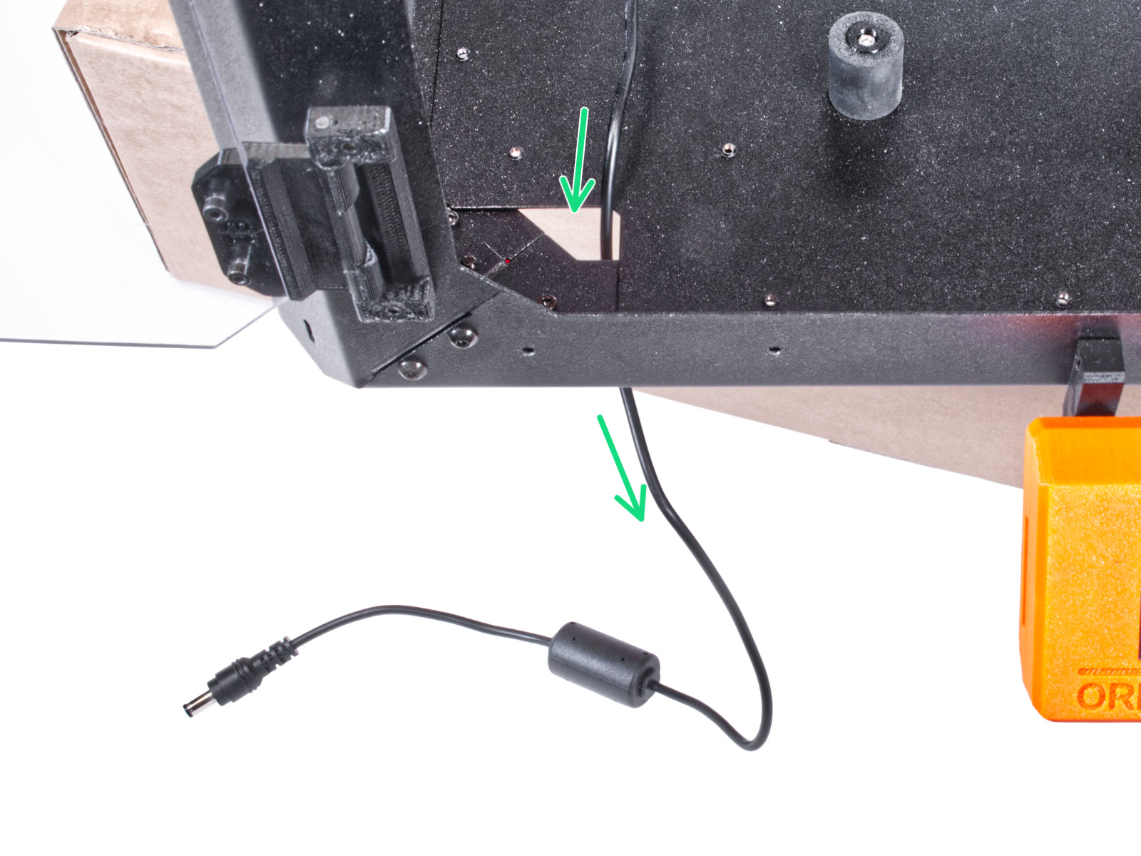
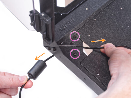
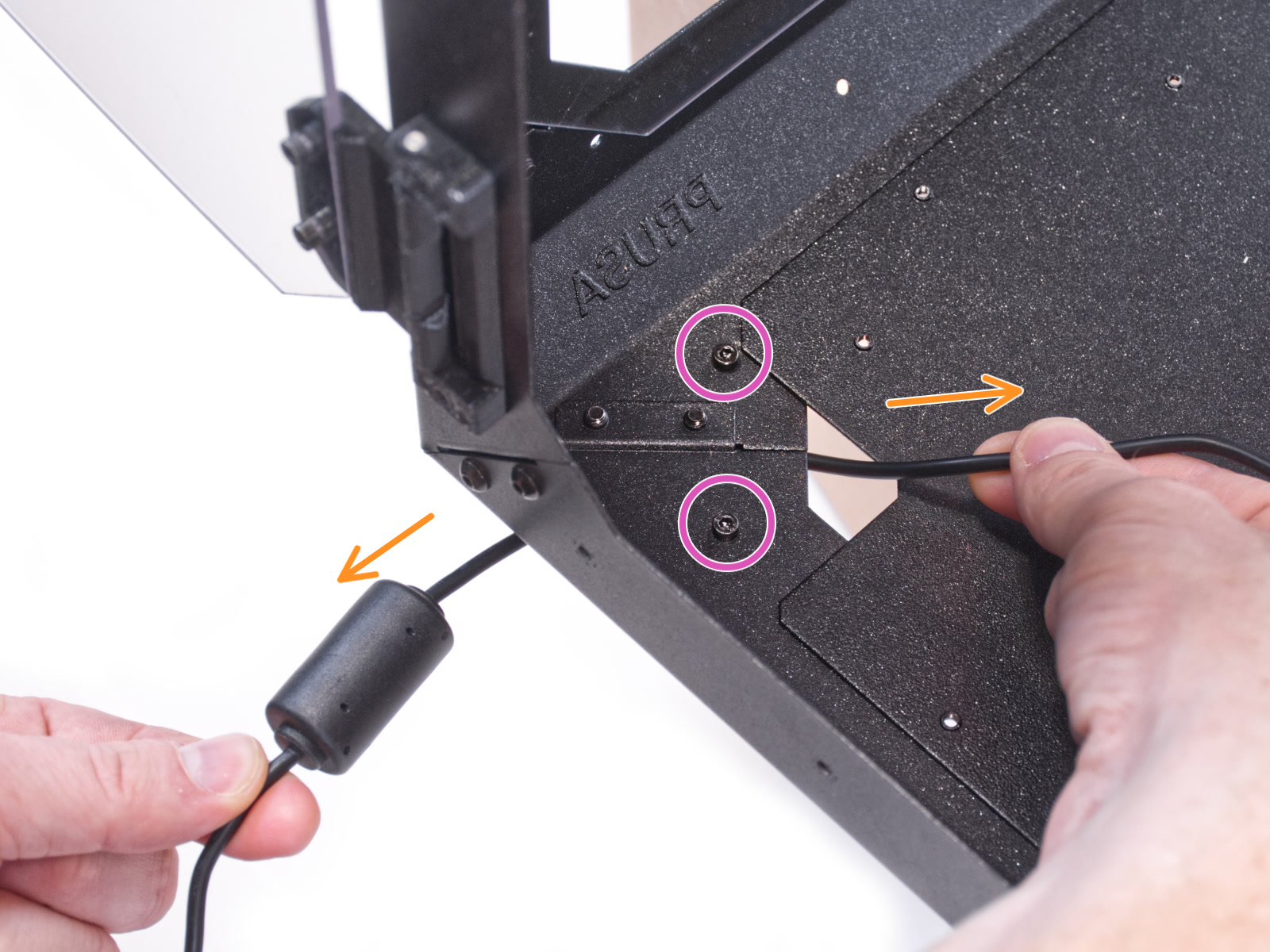
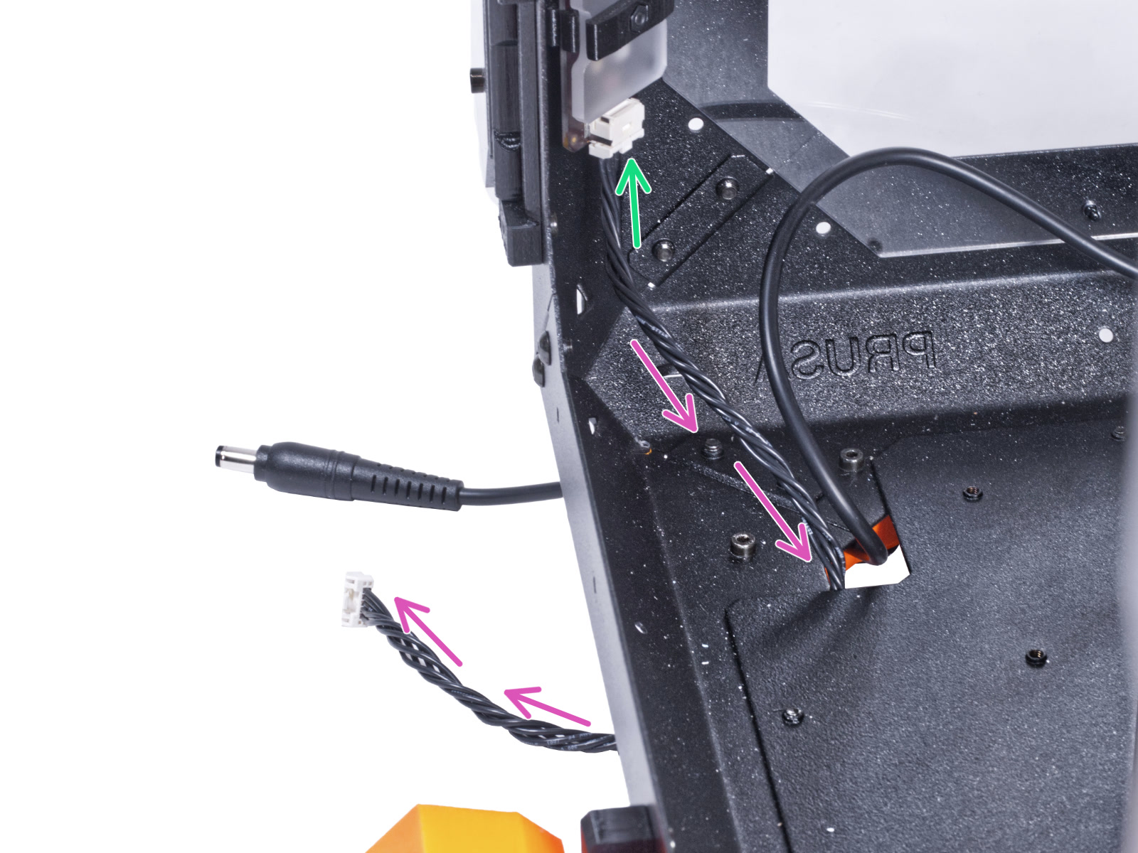
⬢Slightly lift the bottom panel from the bottom side.
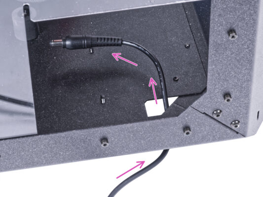
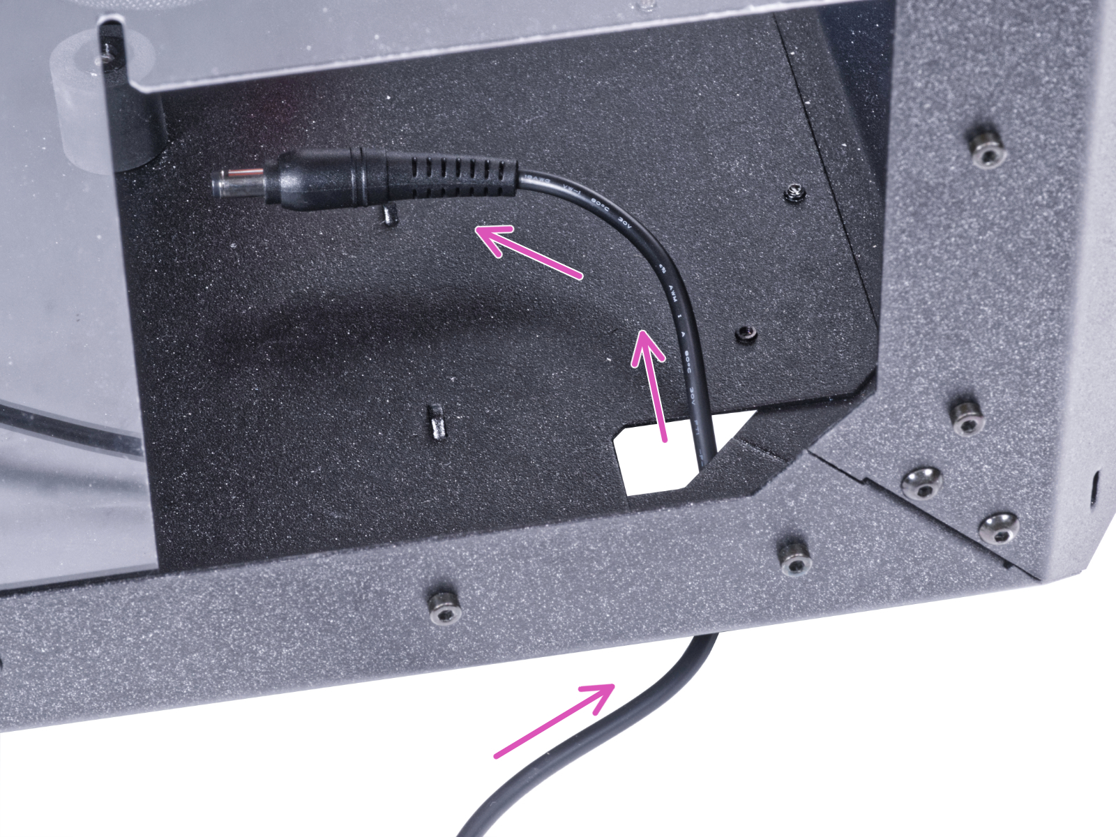
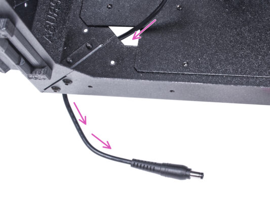
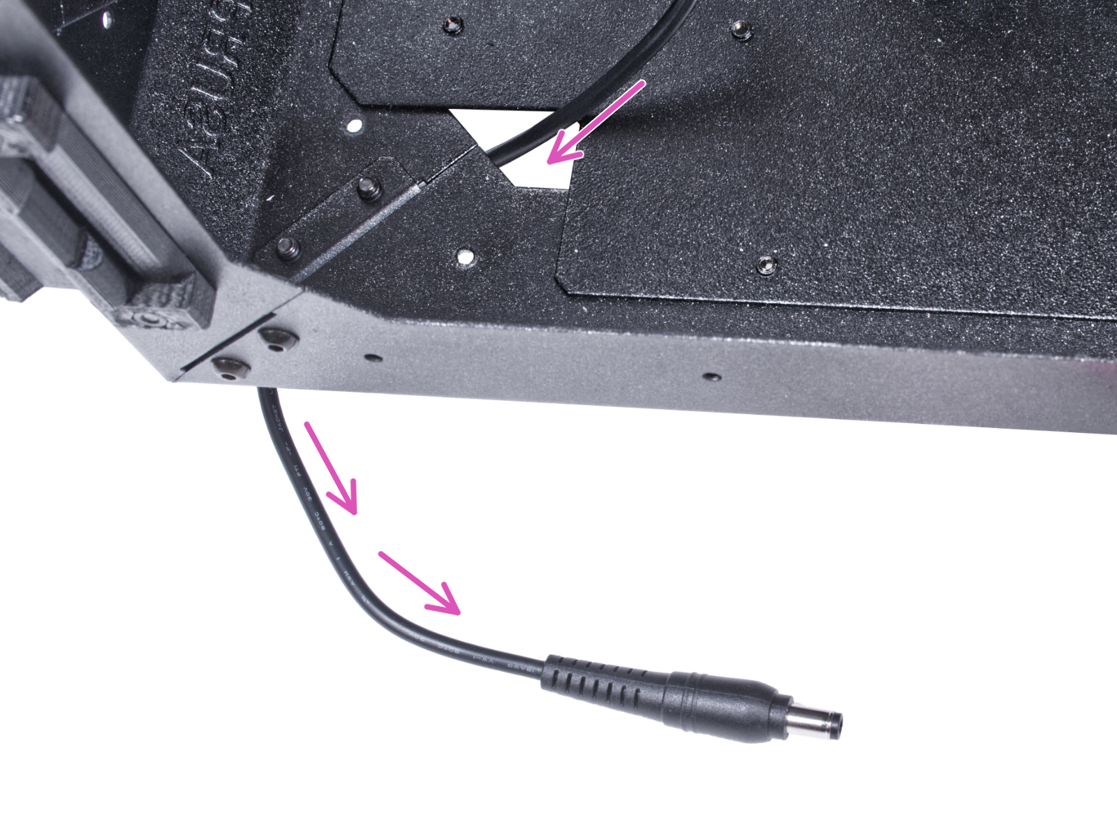
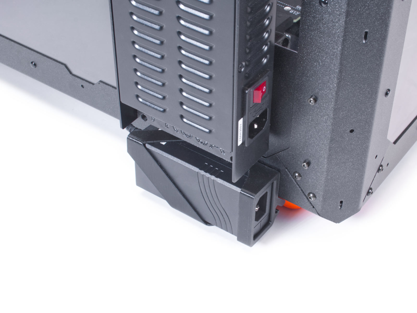
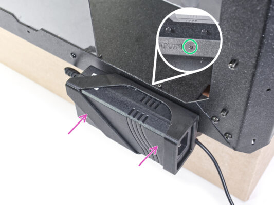
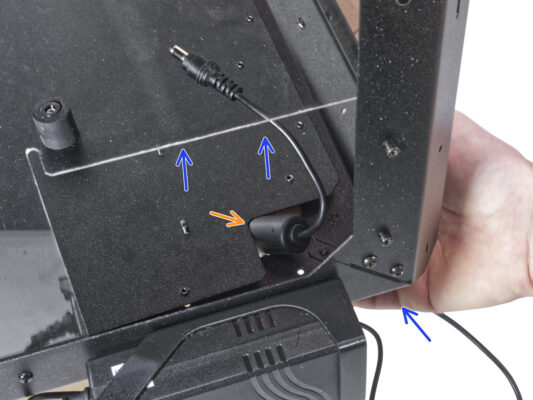
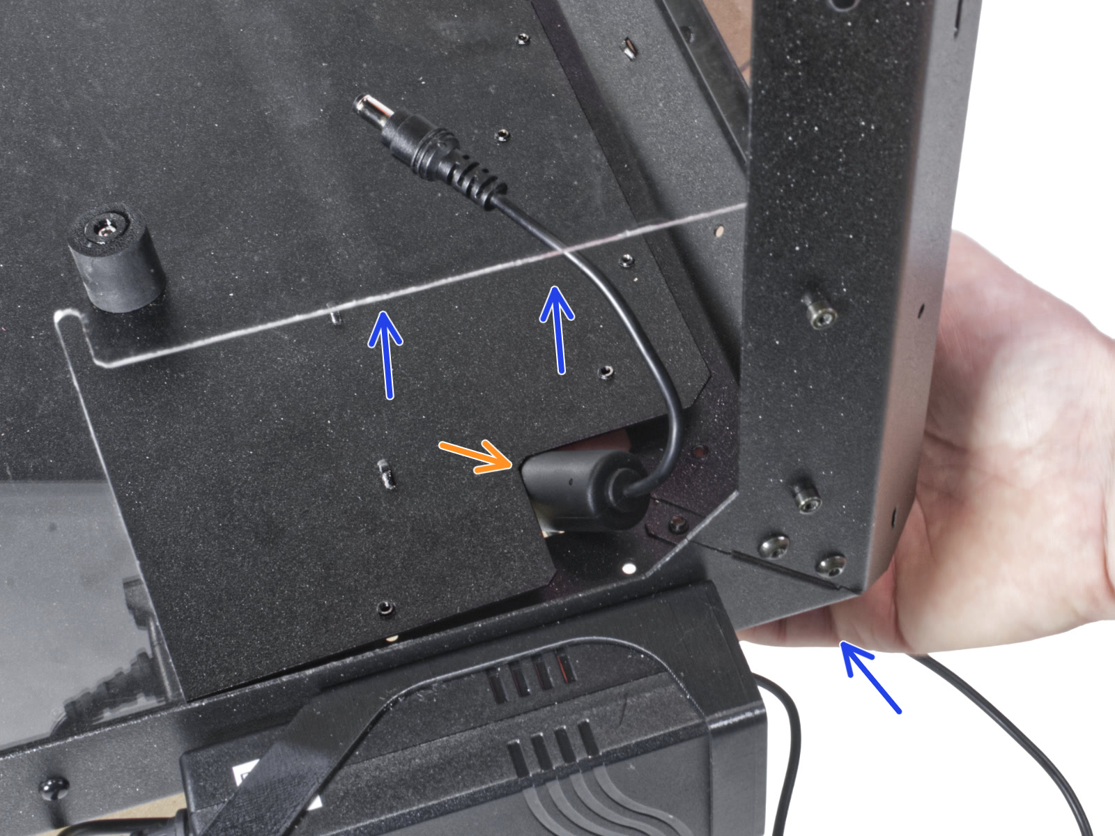
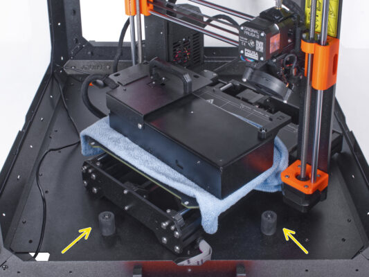
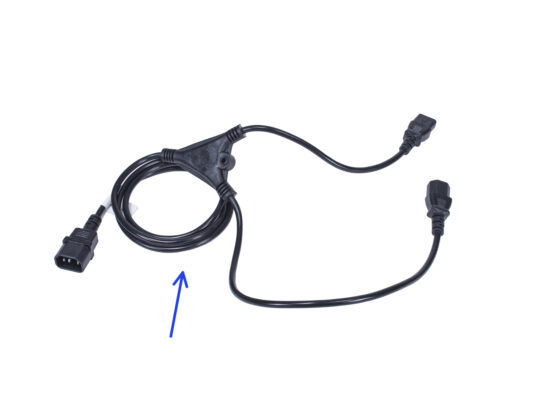
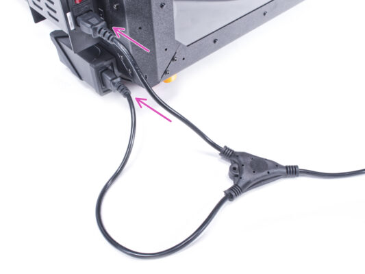
⬢From the bottom side, push the PSU cable with the ferrite bead (cylindrical part) through the hole in the bottom panel into the enclosure.
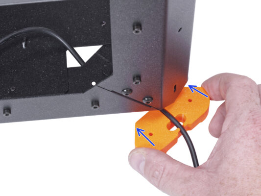
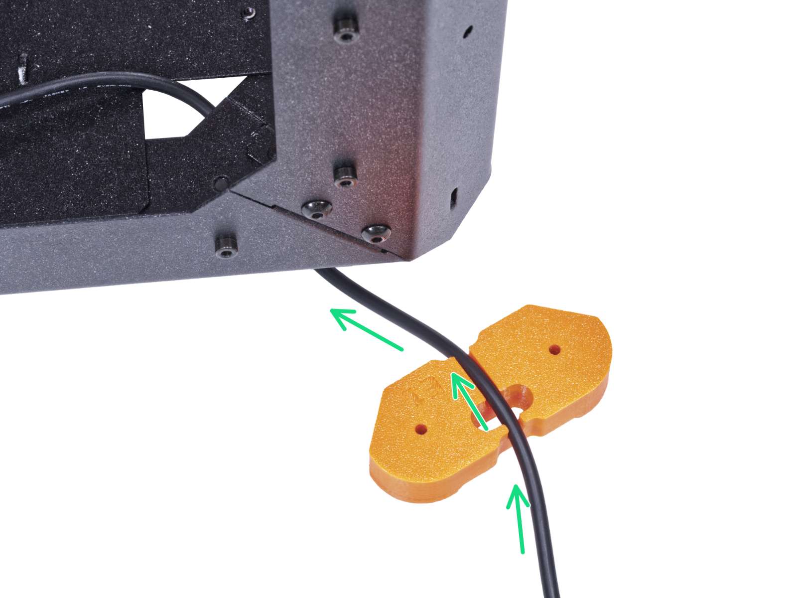
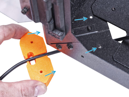
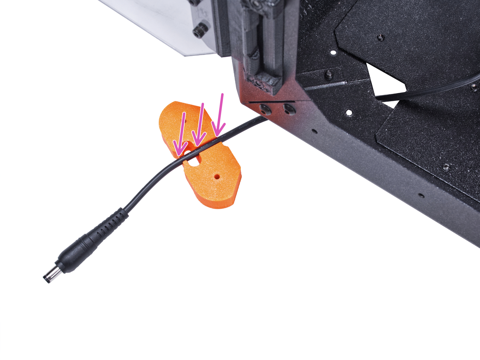
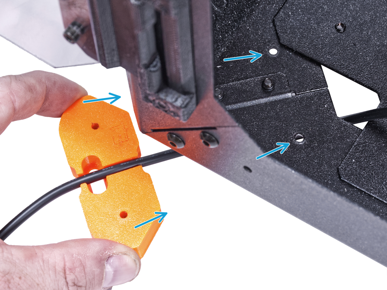
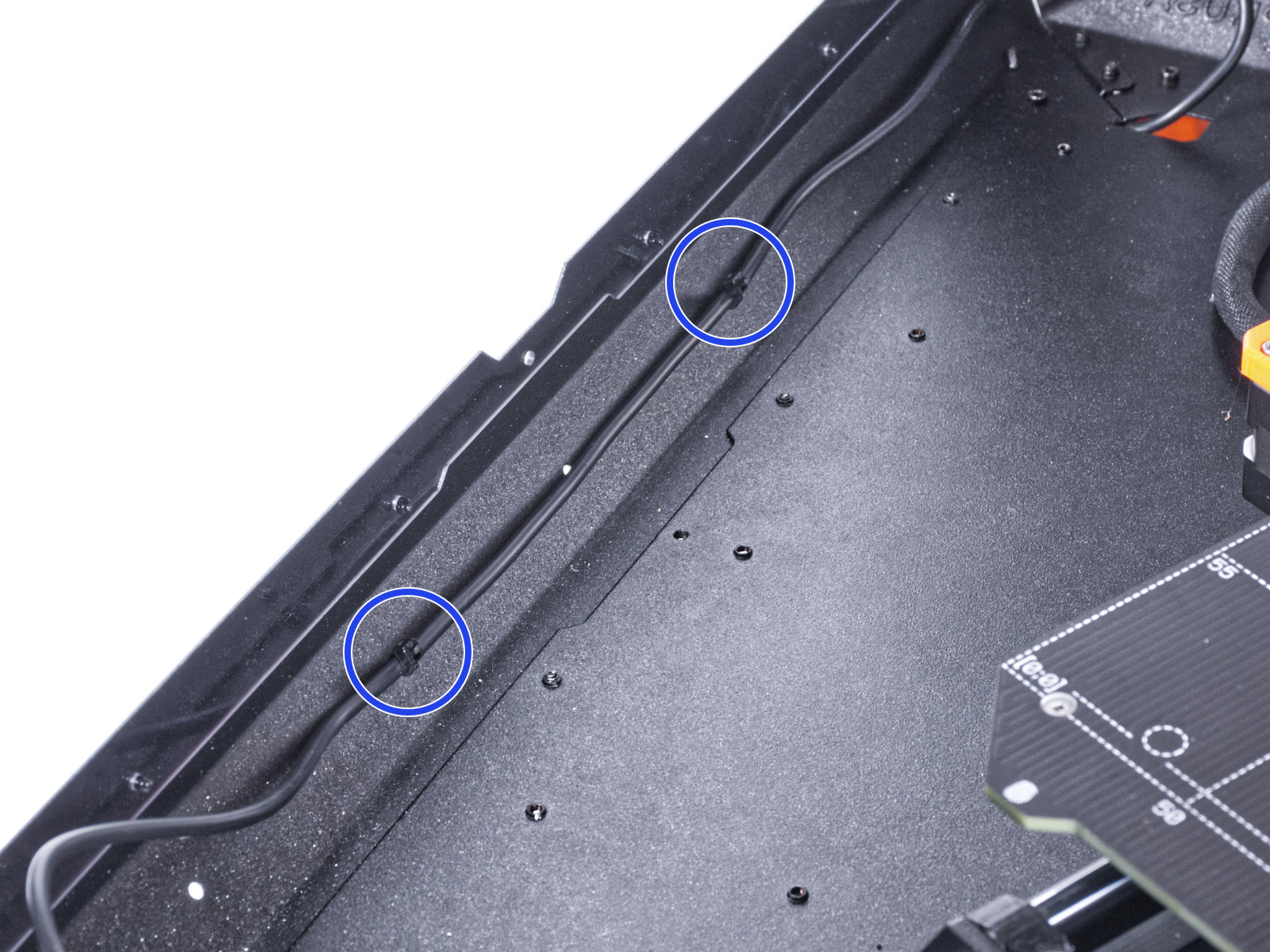
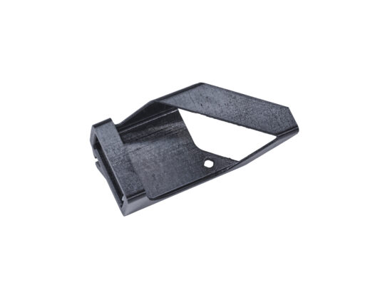
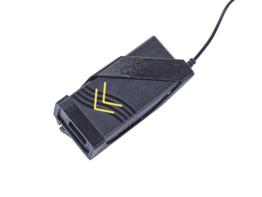
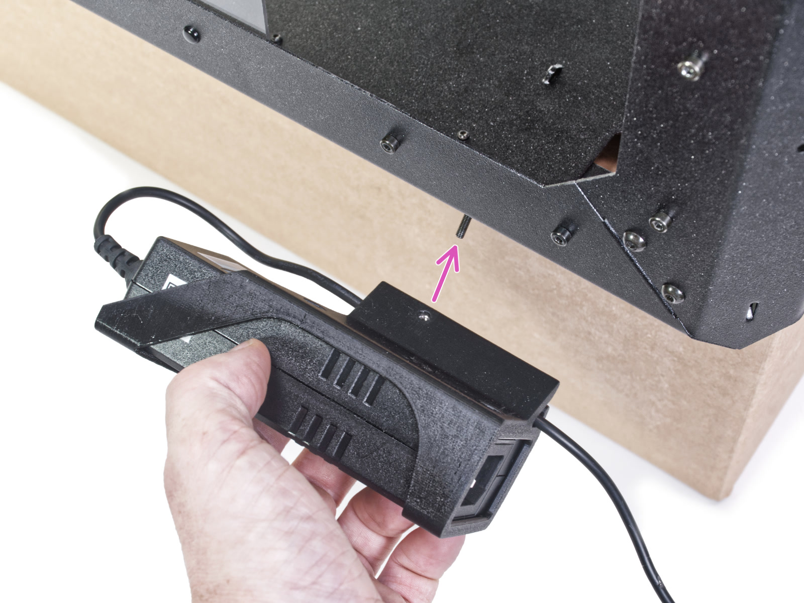
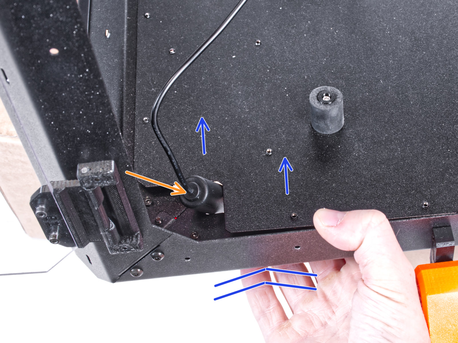
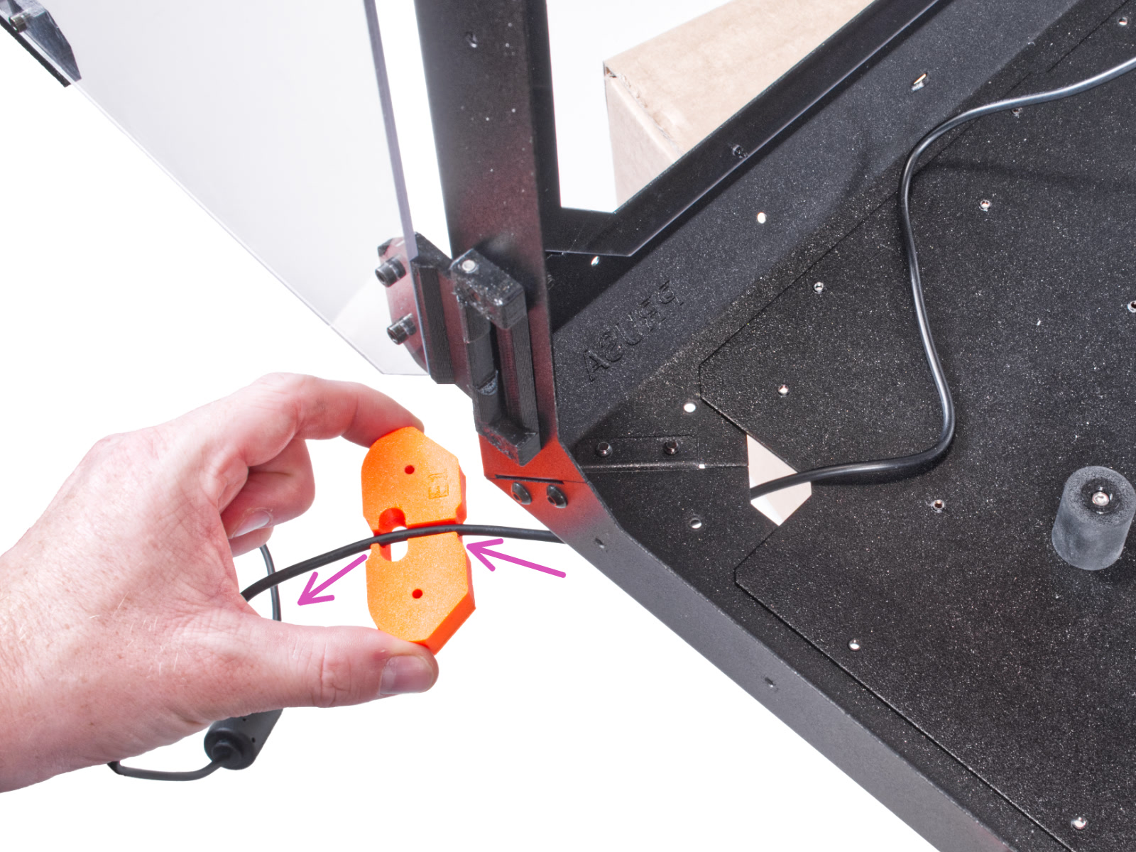
⬢Guide the PSU cable through the channel in the feet bracket. See the correct orientation of the part.
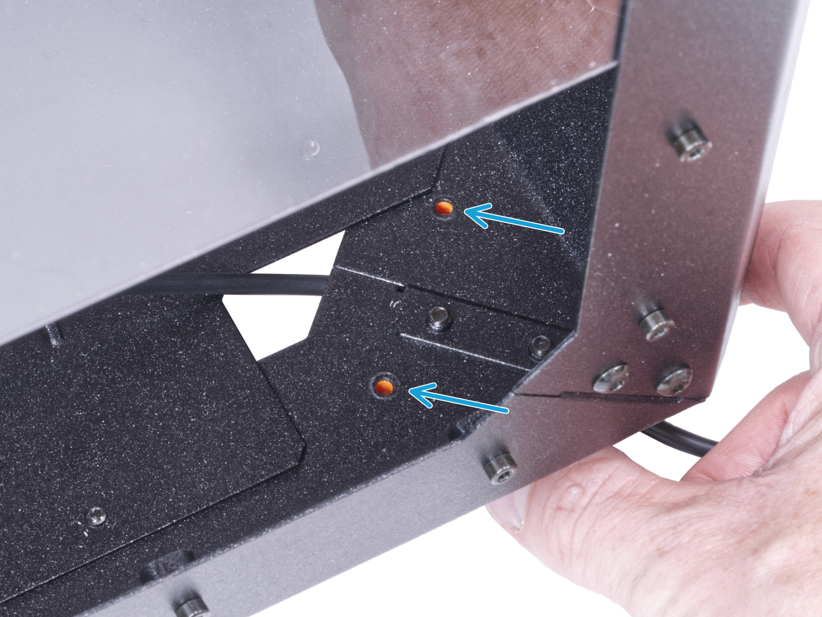
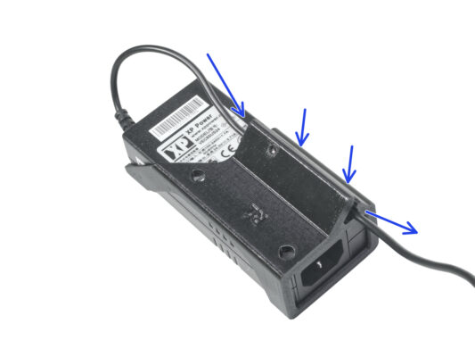
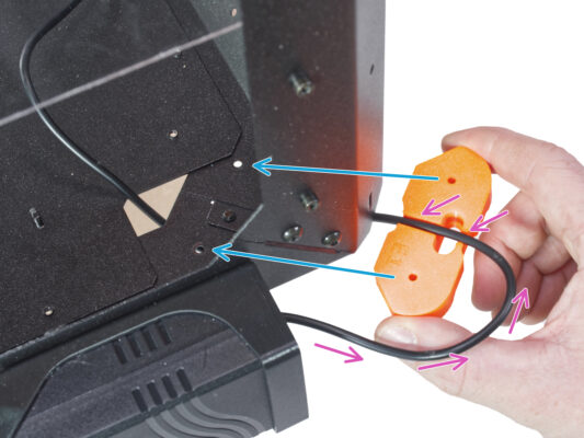
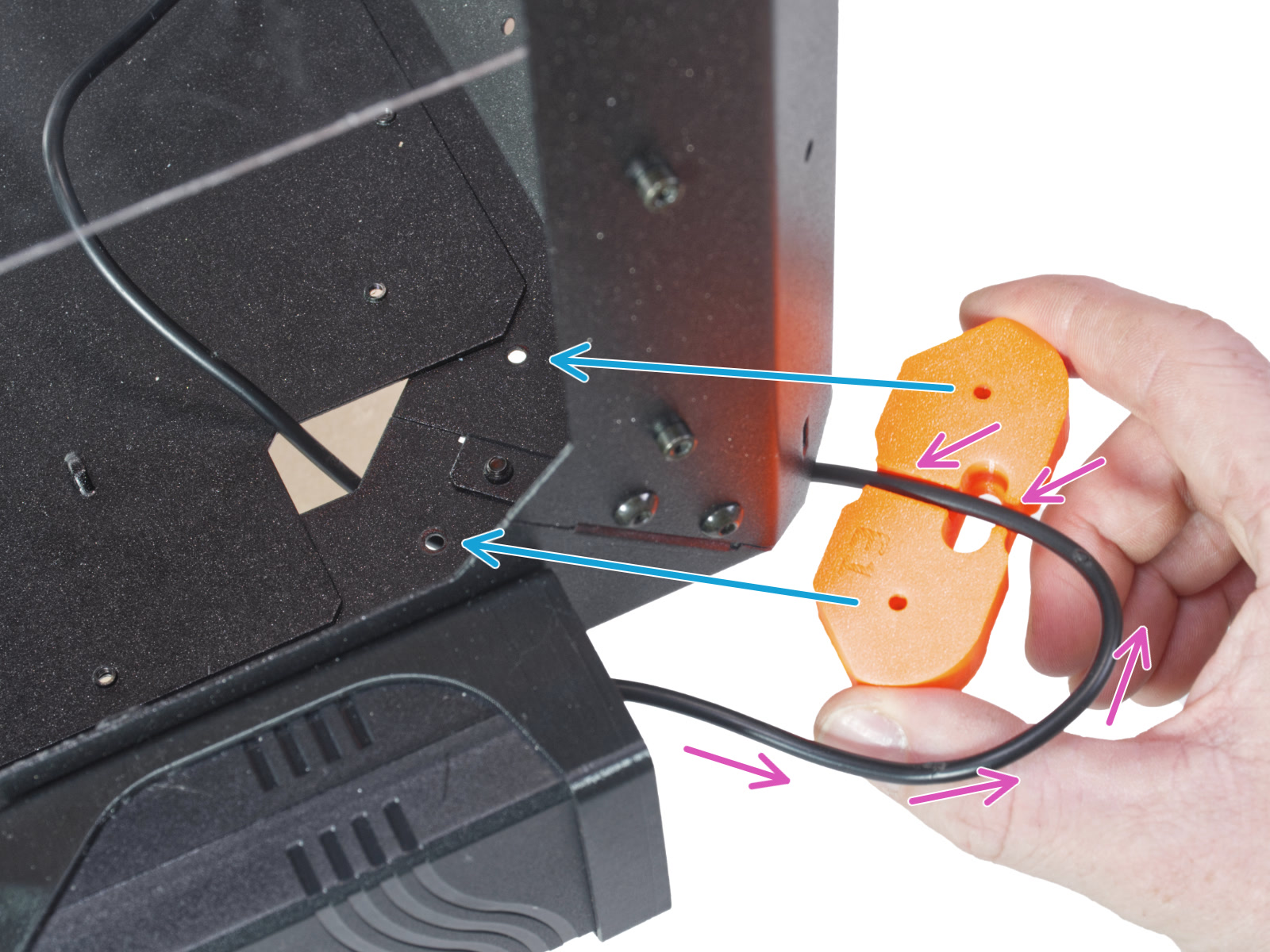
⬢Maintain the orientation of the feet bracket and attach it to its place on the bottom of the enclosure. Line up the holes in the part with the hole in the bottom frame of the enclosure.
⬢Make sure the cable has not fallen out of the channel.
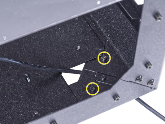
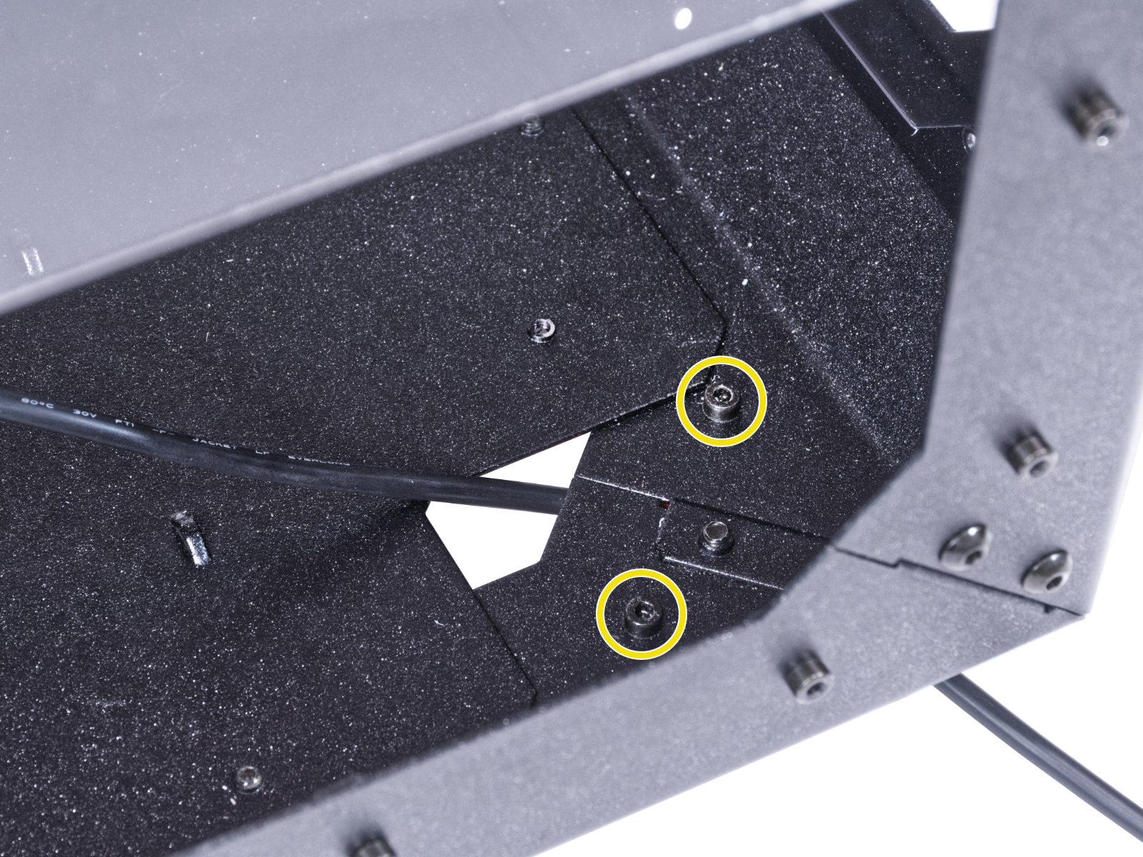
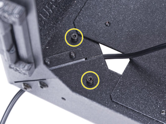
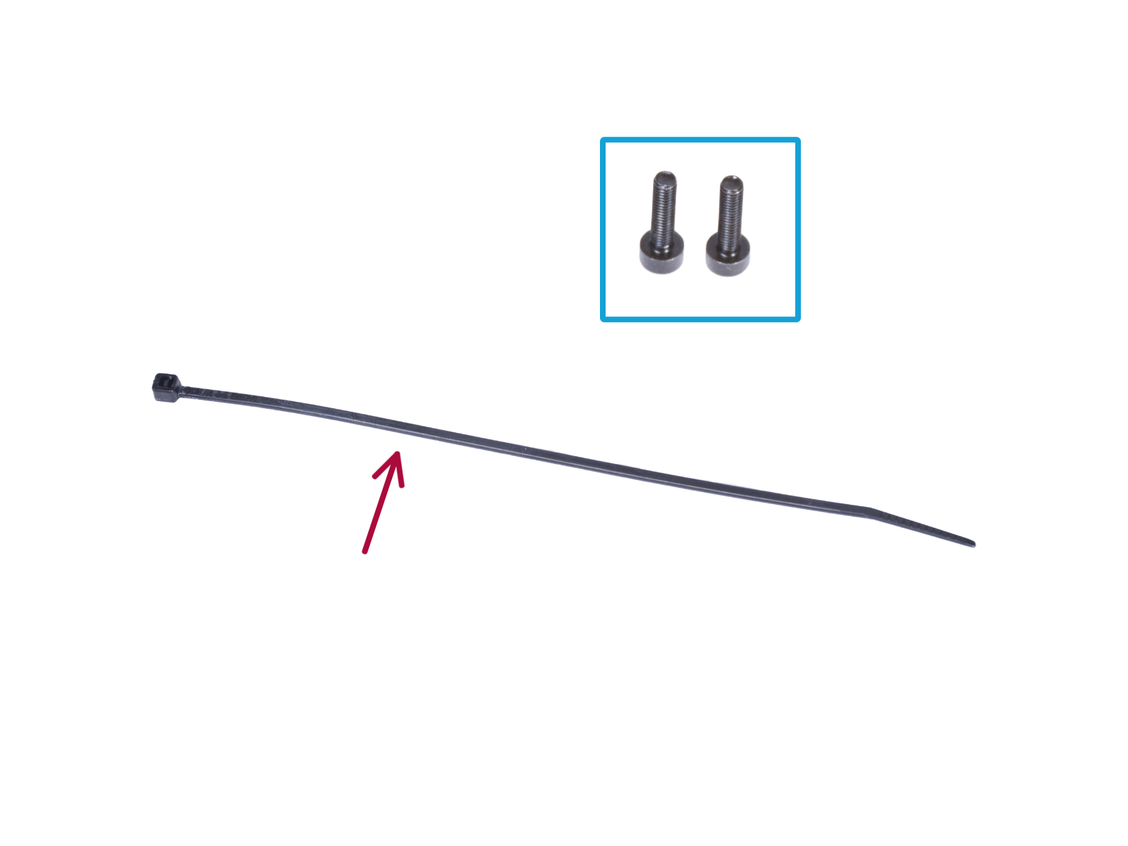
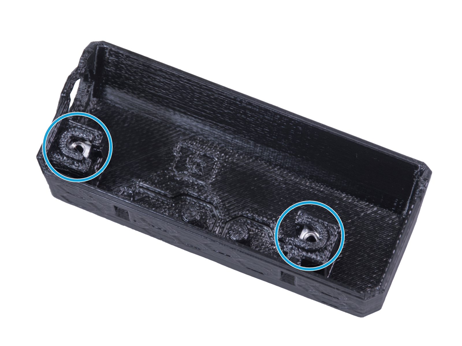
⬢Secure the feet bracket with two M3x12 screws.
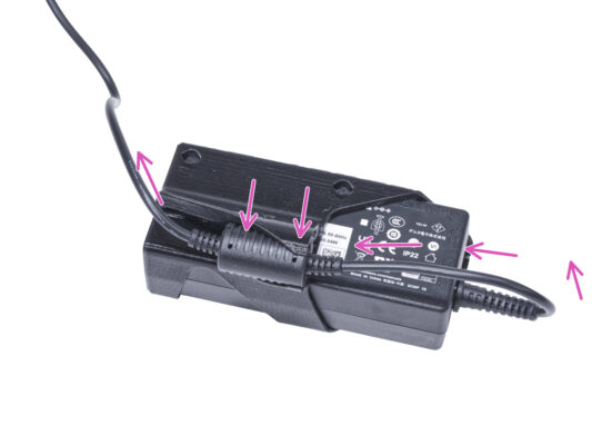
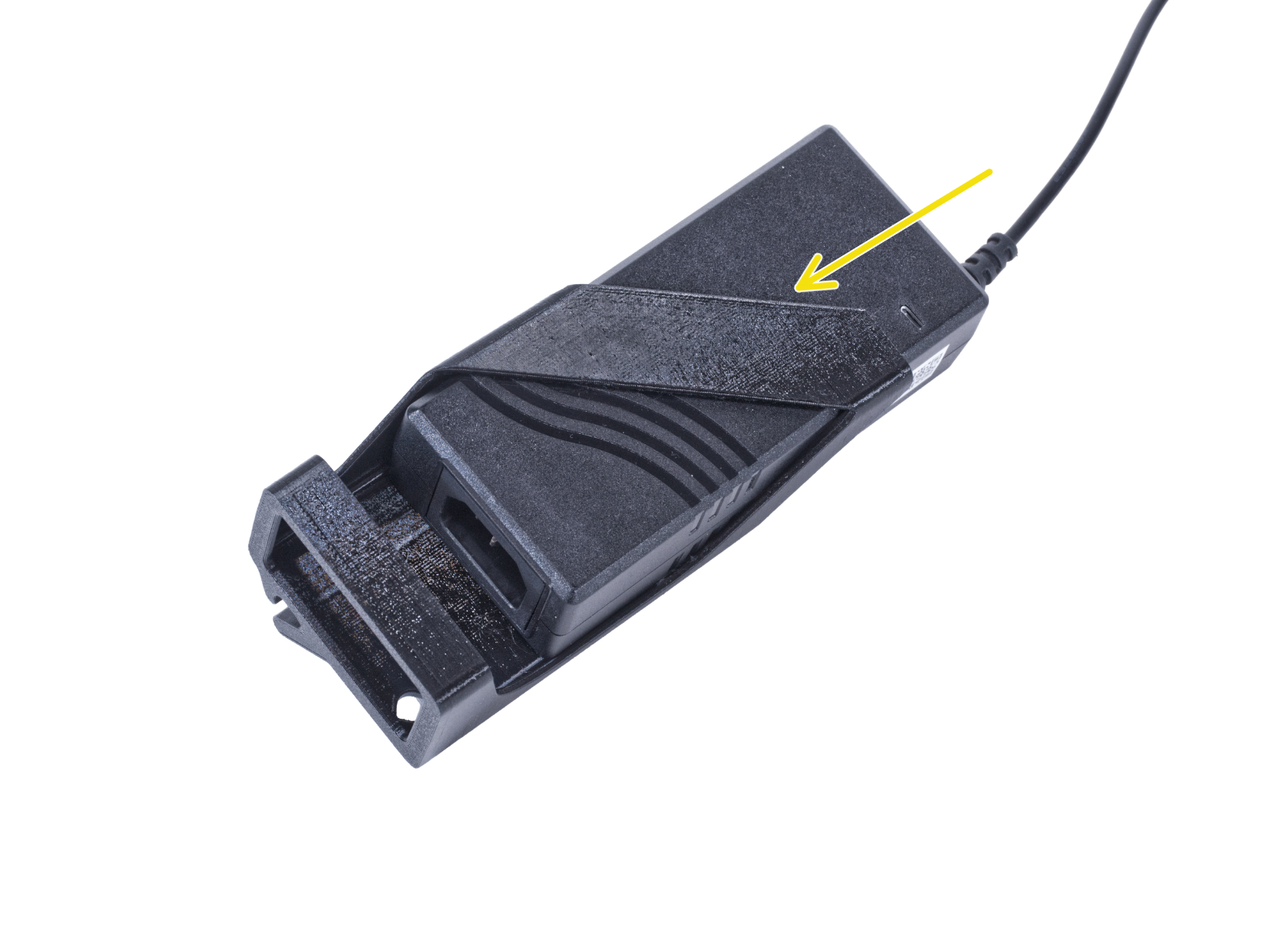
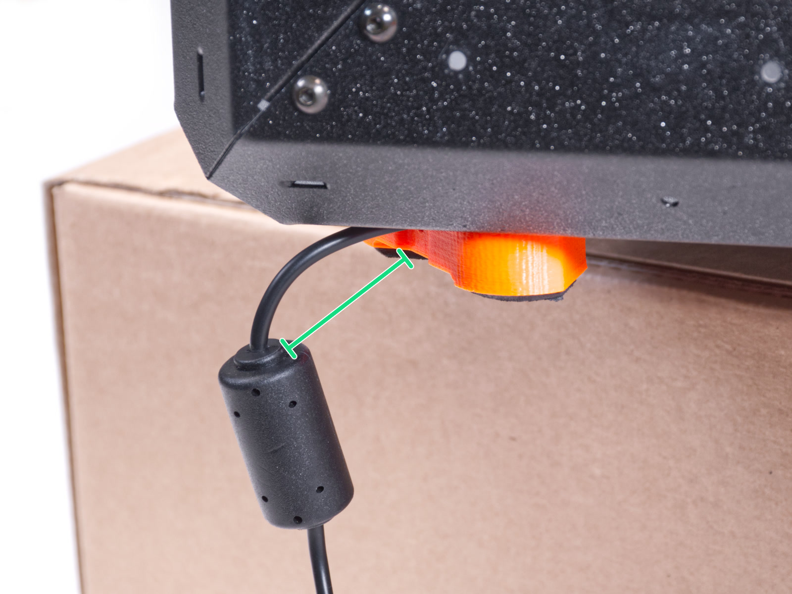
⬢Gently pull the cable back and forth to check for pinching. Keep the excess cable as shown in the picture.
⬢Overhang the rear side of the enclosure over the box or table. It is necessary that both feet on the rear side stand on one anti-vibration pad. Avoid placing the enclosure directly on the frame.
WARNING: Be extra careful and make sure the enclosure is stable and doesn't wobble. Otherwise, the enclosure may fall off the box and hurt you and damage.
⬢Secure the bottom panel with two M3x4 screws from the bottom.
⬢Place the enclosure so that all feet are on the surface.
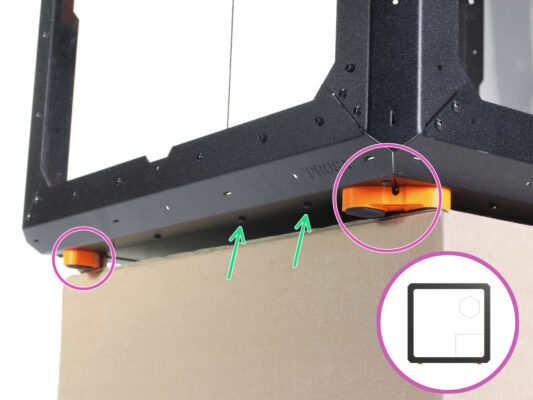
⬢Place the enclosure on the cardboard box with the front side overhanging the box.
⬢It is necessary that both feet on the front side stand on one anti-vibration pad. Avoid placing the enclosure directly on the frame.
WARNING: Be extra careful and make sure the enclosure is stable and doesn't wobble. Otherwise, the enclosure may fall off the box and hurt you and damage.
⬢From the bottom, release first two screws from the left.
⬢Move the left front corner over the edge of the box or table.
⬢Maintain the orientation of the feet bracket and attach it to its place on the bottom of the enclosure. Line up the holes in the part with the hole in the bottom frame of the enclosure.
⬢Make sure the cable has not fallen out of the channel.
⬢Secure the feet bracket with two M3x12 screws.
⬢Gently pull the cable back and forth to check for pinching.
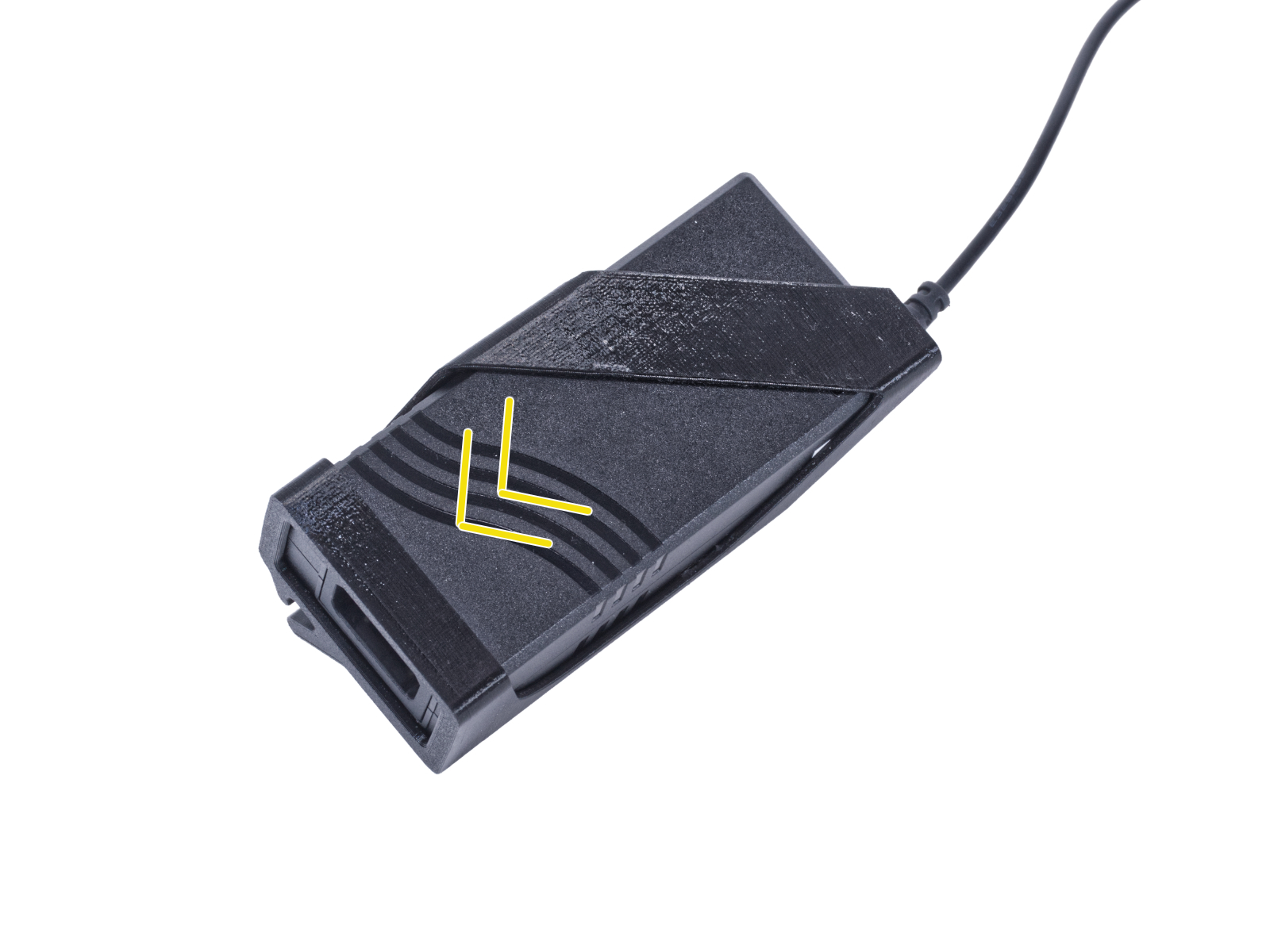
⬢Leave the cable extended as shown in the picture. Space between ferrite bead and the feet bracket between 2 - 5 cm.
⬢Overhang the front side of the enclosure over the box or table. It is necessary that both feet on the front side stand on one anti-vibration pad. Avoid placing the enclosure directly on the frame.
WARNING: Be extra careful and make sure the enclosure is stable and doesn't wobble. Otherwise, the enclosure may fall off the box and hurt you and damage.
⬢Secure the bottom panel with two M3x4 screws from the bottom.
⬢Overhang the left side of the enclosure over the box or table. It is necessary that both feet on the left side stand on one anti-vibration pad. Avoid placing the enclosure directly on the frame.
⬢Secure the bottom panel with four M3x4 screws from the bottom.
⬢Now, place the enclosure on all its feet on the work table and remove the cardboard box. We will not need it anymore.
The nut must be completely embedded in the printed part and flush with the surface of the part. Insufficient embedment of the nut can cause problems when mounting in the enclosure.
⬢Slide the lower slot of the LED Stick Bracket on the LED Stick Board and align the bracket against the first hole in the LED Stick Board closest to the (white) LED stick connector.
Avoid sliding the bracket over chips and diodes! It can be fatally damaged.
⬢Push the LED Stick Bracket all the way on the LED Stick Board.
⬢Use this procedure for all three LED Stick Brackets.
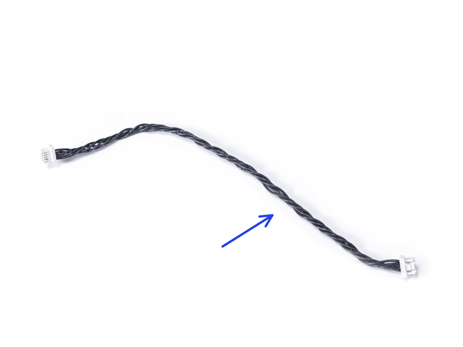
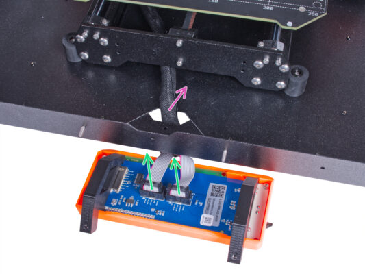
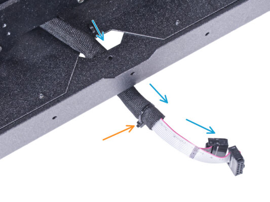
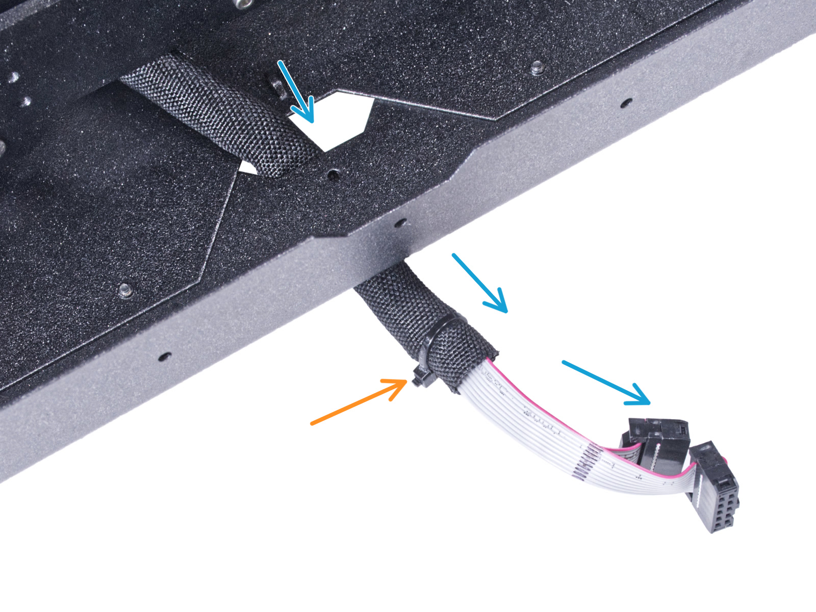
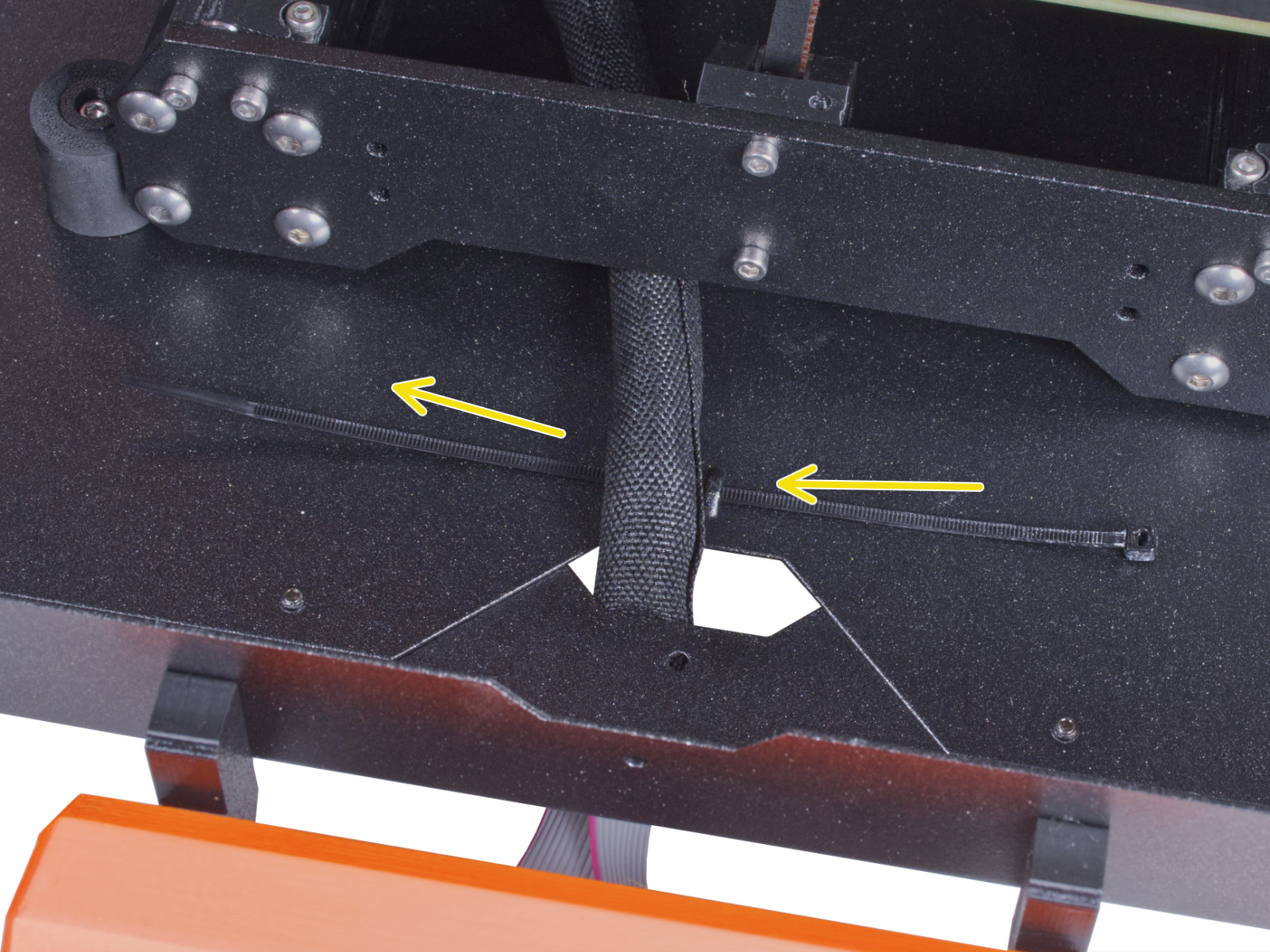
⬢Guide the LCD cable through the cutout in the bottom panel.
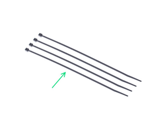
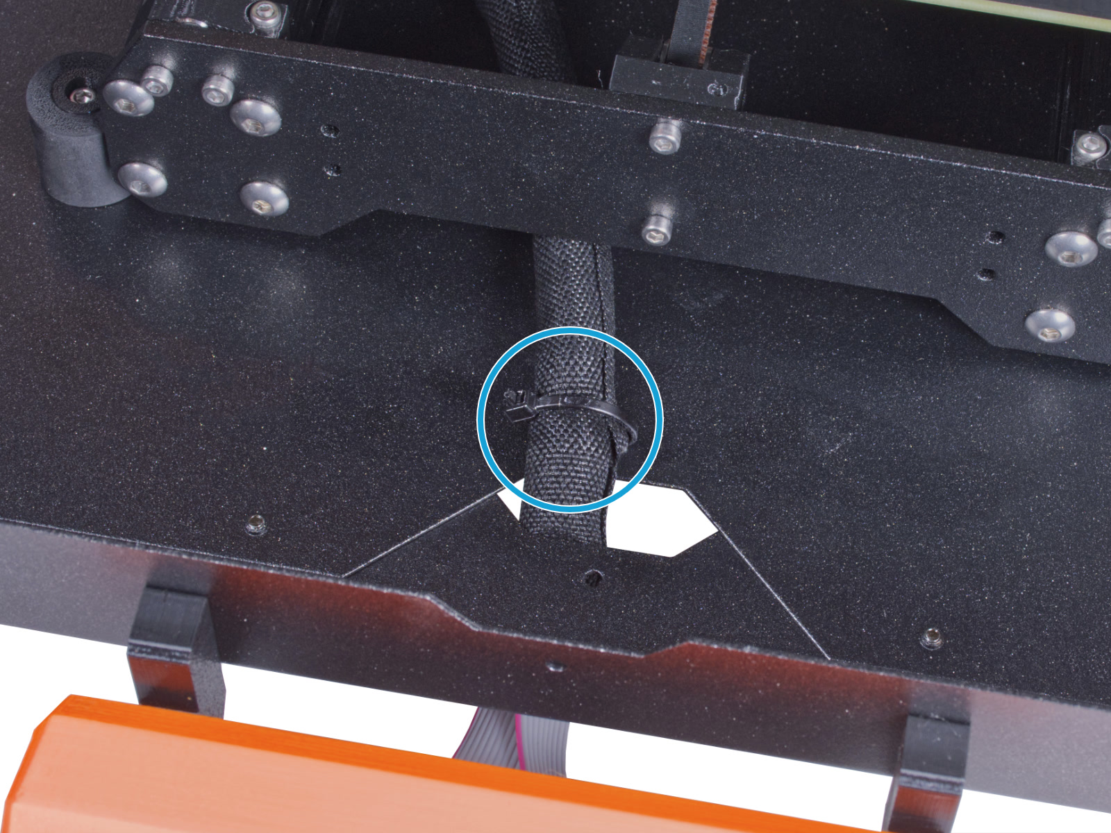
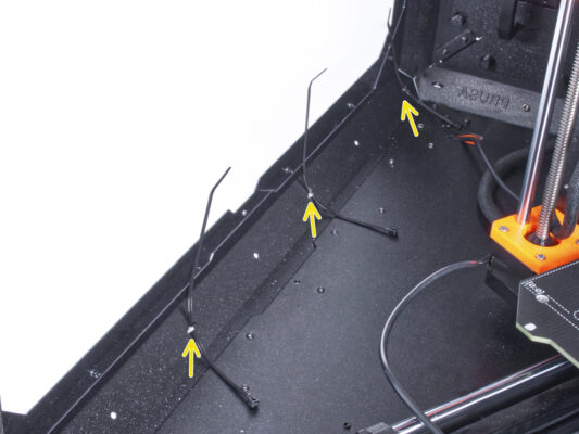
⬢Secure the textile sleeve on the cable bundle with the zip tie. Do not over tighten the zip tie, it may cut the cables!
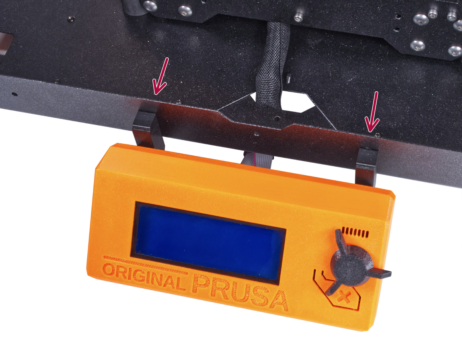
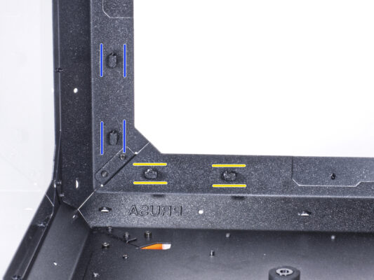
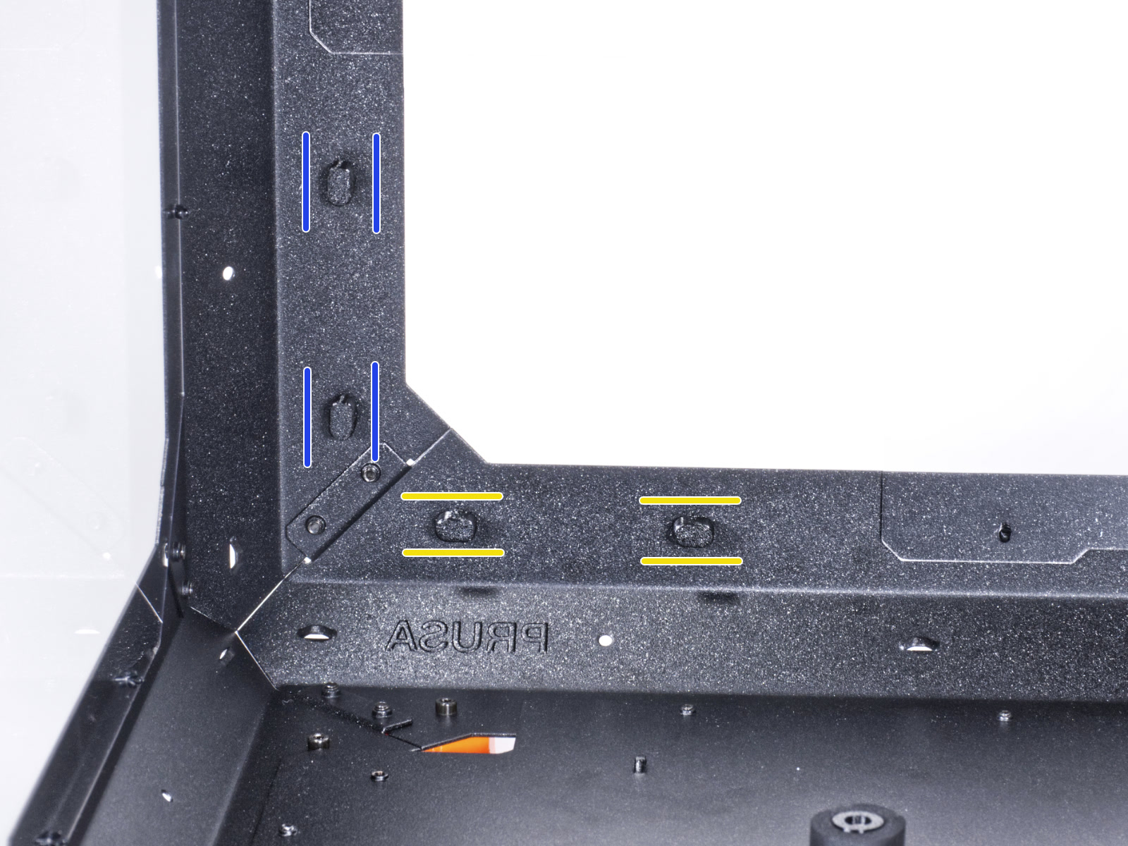
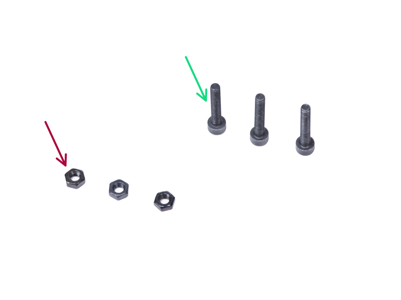
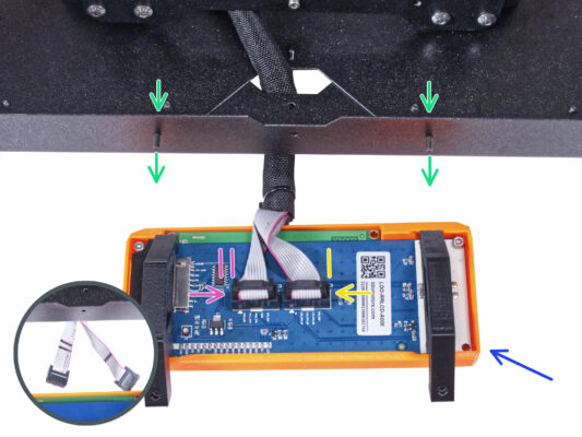
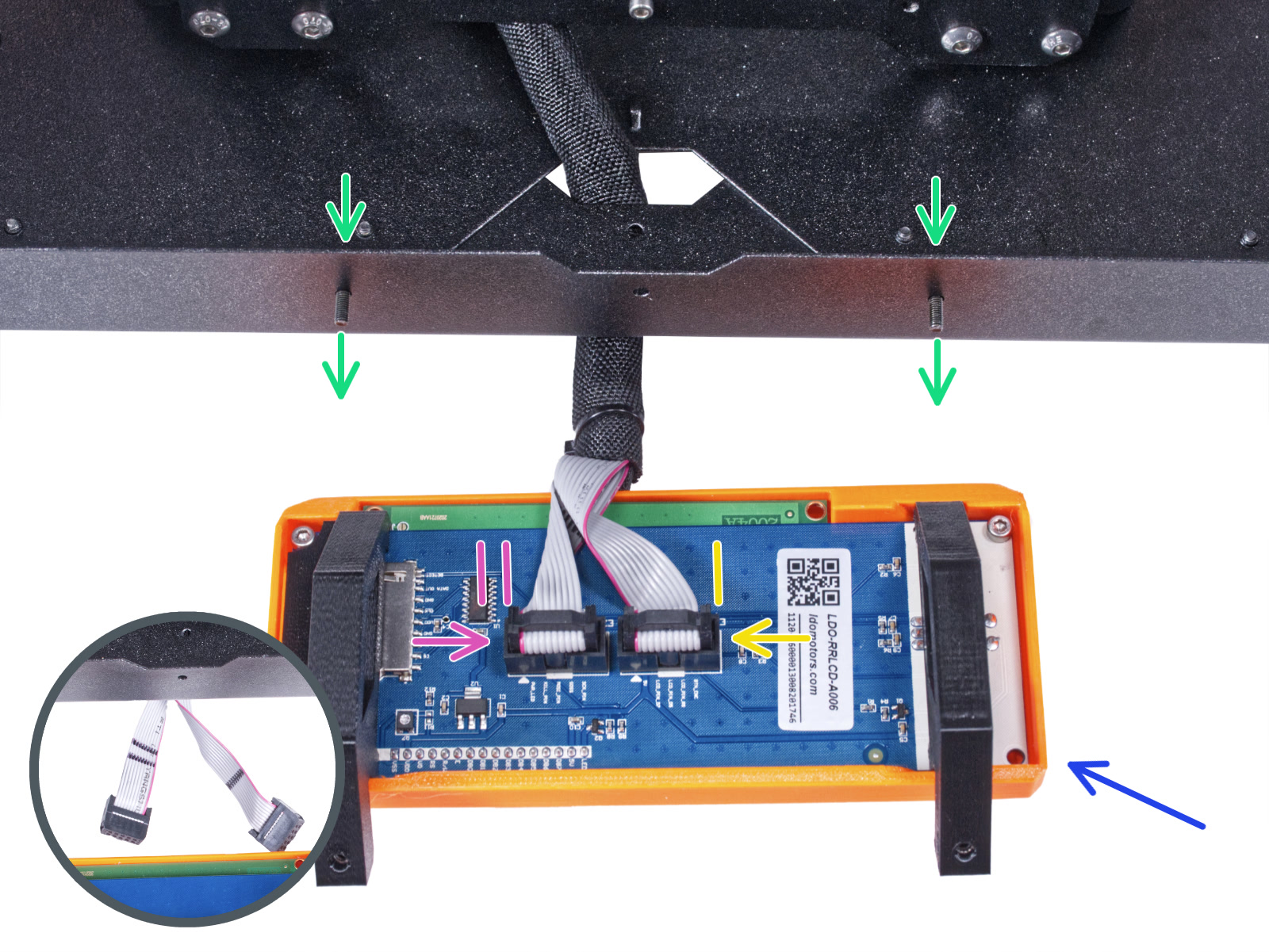
⬢From the inside, push two M3x8 screws through the bottom profile.
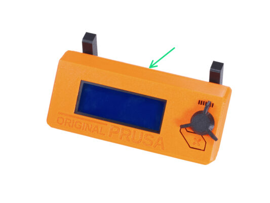
⬢Place the LCD assembly close to the LCD cables, like in the picture. Mind the same orientation of the LCD as in the picture. See the LCD-supports for better understanding.
Note that both cables are marked with stripes on one side. Correct connection order is important!
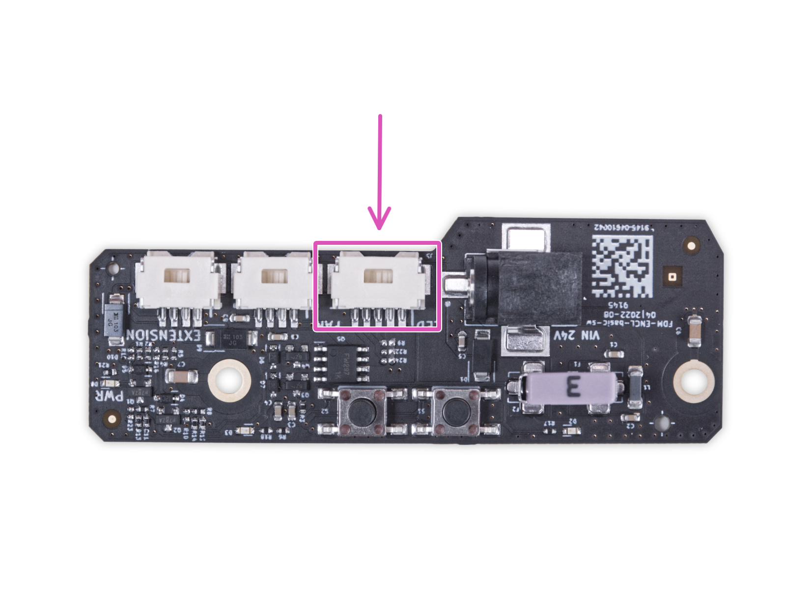
⬢Connect the LCD cable marked with TWO STRIPES to the left slot (called EXP2) on the LCD controller.
⬢Connect the LCD cable marked with ONE STRIPE to the right slot (called EXP1) on the LCD controller.
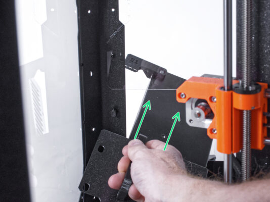
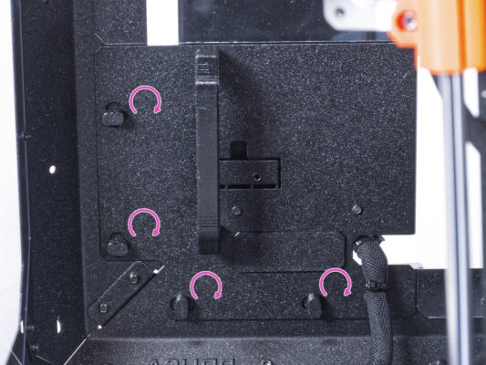
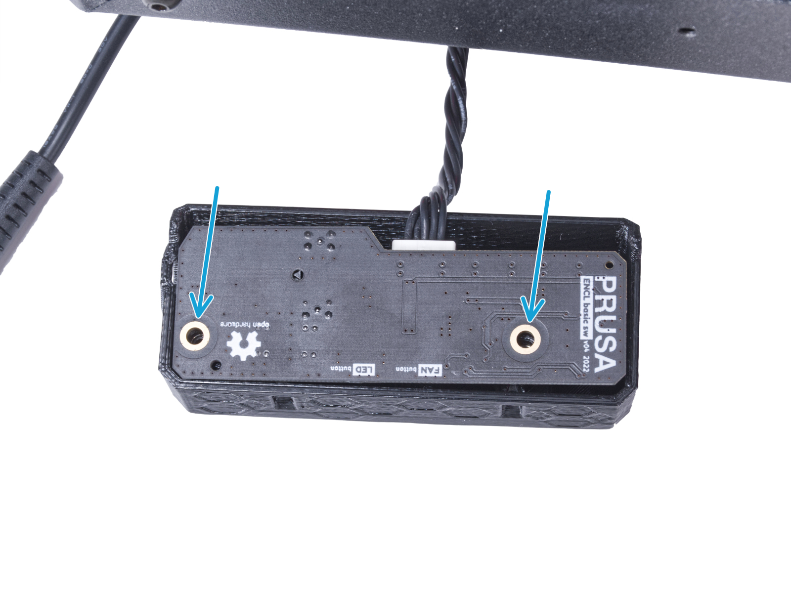
⬢Slide the LCD assembly onto the two M3x8 screws in the frame and tighten them.
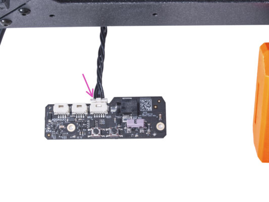
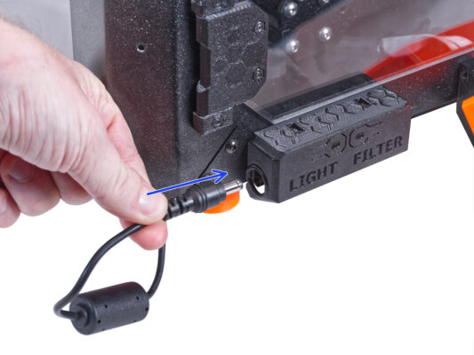
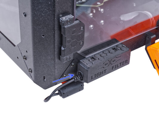
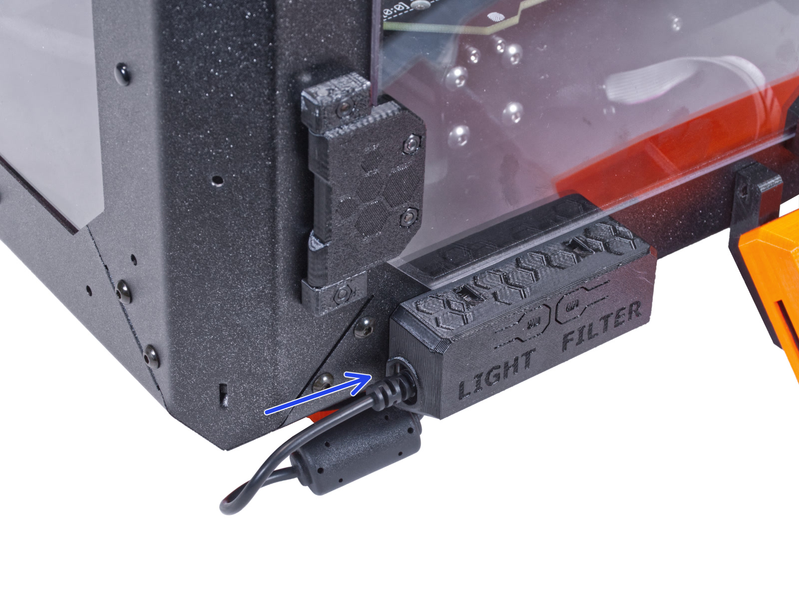
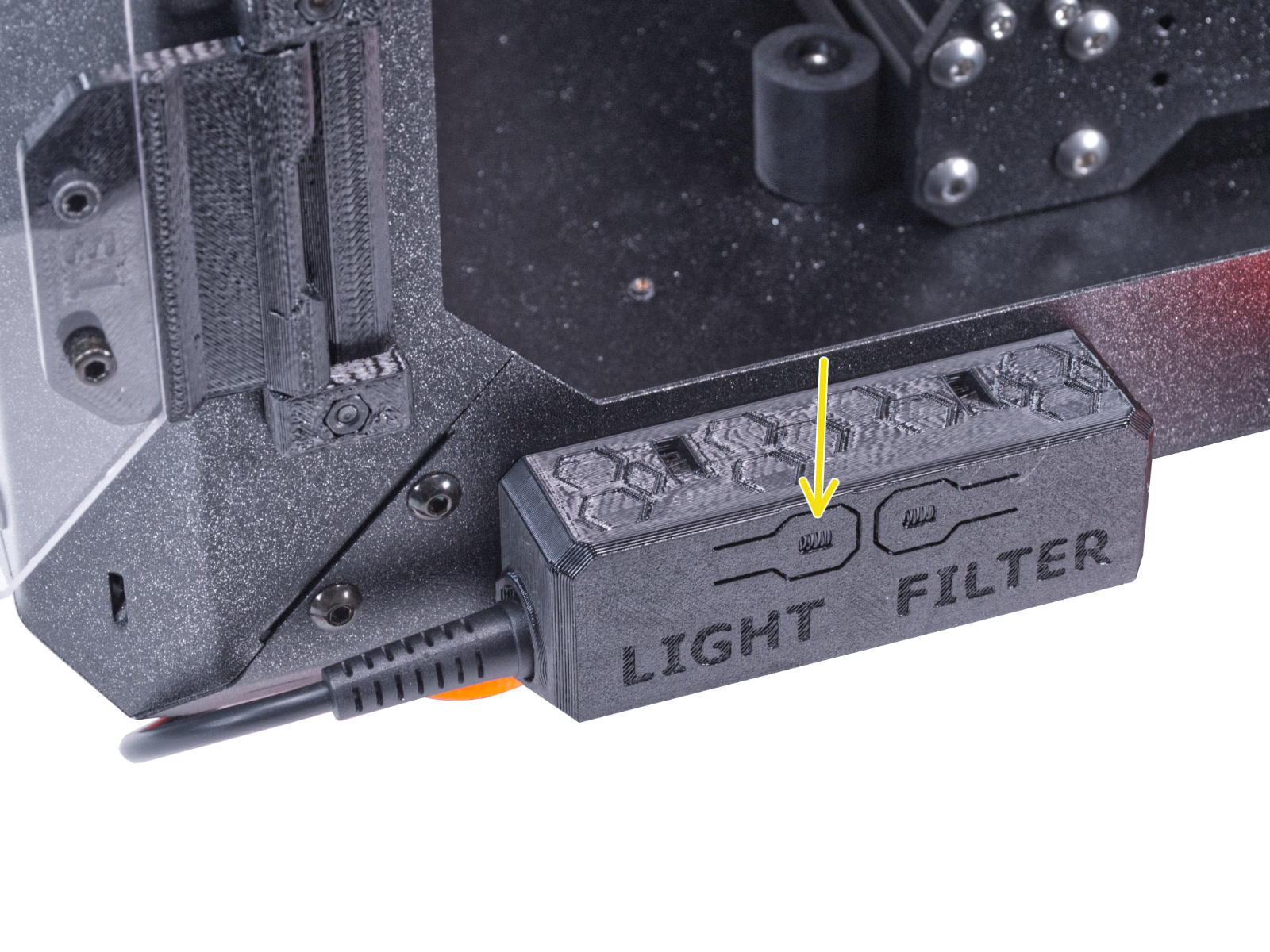
⬢Check if it works properly. Press the LIGHT button on the Basic Board Panel and check if the LED lighting inside has turned on.
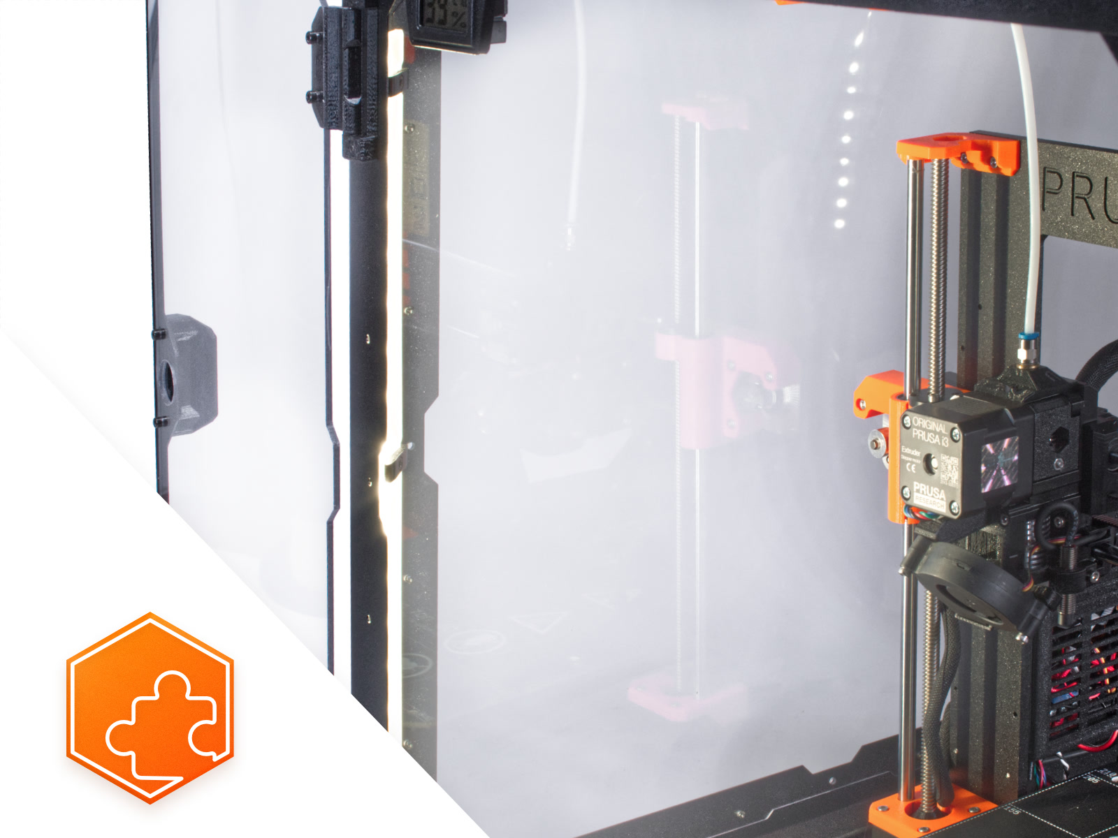
⬢Nice job! The LED strip is successfully installed.
Was this guide helpful?
Comments
Still have questions?
If you have a question about something that isn't covered here, check out our additional resources. And if that doesn't do the trick, you can send an inquiry to [email protected] or through the button below.