English
Login
3D printers
Materials
Parts & Accessories
For Business
Software
3D Models
Community
Help
Courses
Blog
Company
Support
Original Prusa XL
Original Prusa XL Single-Tool (Semi-Assembled) (1.07)
2. Base & Side frame assembly | Tools necessary for the next steps
1. Tools necessary for the next steps
Step 1 of 36 (Chapter 2 of 7)
Contents
Comments
⬢
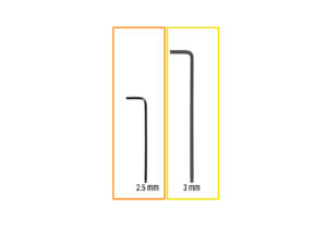
For this guide, please prepare:
⬢
2.5mm Allen key
⬢
3mm Allen key
Loading...
Next
Contents
Original Prusa XL Single-Tool (Semi-Assembled)
1. Introduction
2. Base & Side frame assembly
Tools necessary for the next steps
Base frame parts preparation
Extrusion alignment
Right rear extrusion assembly
Securing the right rear extrusion
Left rear extrusion assembly
Z-Axis assembly clarification
Z-Axis fixed assembly
Securing the Z-Axis fixed
Z-Axis rotary assembly
Securing the Z-Axis rotary
Torque indicator: parts preparation
Assembling the Torque indicator
Final tightening with torque indicator
Haribo time!
xLCD: parts preparation
xLCD cable covers: parts preparation
Extrusion covers: parts preparation
Mounting the xLCD
Aligning the xLCD
xLCD assembly versions
Version A: Installing the xLCD PE cable
Version B: Installing the xLCD PE cable
xLCD PE cable management
xLCD cable routing
Routing the cables
Routing the cables
Routing the cables
Horizontal cable inserting
Corner frame cover
Inserting Z-motor-cable-bottom-cover
Preparing the cables for rear cover
Inserting the second motor cable
Inserting Z-motor-cable-bottom-cover
Haribo time!
Well done!
3. CoreXY & Back assembly
4. Heatbed & Side panels assembly
5. Nextruder & accessories assembly
6. First run
Manual changelog
Comments
Log in
to post a comment
No comments