EN
  • Čeština
  • Español
  • Italiano
  • Deutsch
  • Polski
  • Français
  • 日本語
Login

2. Disassembly

2. Disassembly
Relevant for:
Last updated 4 years ago
2. Disassembly
 Difficulty
Moderate
 Steps
15
 Available languages
CSPLESDEITFRJA
Preparing the printer
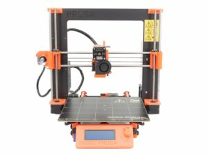
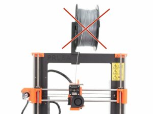
Make sure the filament is unloaded from the hotend and the printer is unplugged!
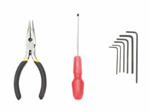
Prepare tools included in the MK2/S kit or get similar from the nearest hardware shop.
We strongly recommend getting a box for the parts. You will need some of them later during assembly.
Y-axis: motor and heatbed disassembly (part 1)
Ensure again the printer is not connected to the power outlet, otherwise, there is a risk of damage to the electronics!
Turn left part of the printer with the RAMBo cover towards you. Release the M3x40 screw using a 2.5mm Allen key.
Open the RAMBo-cover-door and unplug ALL CABLES from the RAMBo board. Proceed carefully, unplug the connector, DO NOT PULL the cable!
In case of any zip ties inside the RAMBo cover (cable management), cut and remove them.
Note there are safety pins on the some connectors (mainly motors), you need to press them before you can unplug the cables.
Y-axis: motor and heatbed disassembly (part 2)
Lay the printer on the PSU side and move the heatbed almost all the way to the back for better stability.
Press the belt down and out from the Y-belt-holder to release the tension in the belt, so you can remove the Y-axis motor.
Cut the zip ties holding the Y-axis motor cables all the way to the RAMBo cover.
Using 2mm Allen key release all four screws holding the heatbed.
Using 2.5 Allen key release both M3 screws in the Y-belt-holder. While releasing the second one, hold the heatbed. Otherwise it will fall down!
Cut the zip tie on the spiral wrap near the RAMBo case and remove the heatbed completely.
Y-axis: motor and heatbed disassembly (part 3)
Turn the printer back, move the heatbed back to front and release the screws holding the endstop and move it away.
Release both screws holding the Y-axis motor, leave the pulley on and move the motor aside.
OPTIONAL: Release all six nylock nuts (M3nN) and remove the Y-carriage. Collect the U-bolts (3x) and keep them for later.
Y-axis: idler disassembly
Using 2.5 mm Allen key M3 remove the screw from the Y-axis idler.
Take out the 623h housing bearing and keep it for later.
Extruder removal (part 1)
Using pliers, cut the zip tie holding the cables from the Extruder. Proceed carefully, you can break the cables.
Using pliers, cut the zip ties on the spiral wrap behind Extruder. Again proceed carefully, you can break the cables. Unwrap the spiral wrap all the way to the RAMBo cover.
Extruder removal (part 2)
Using pliers, cut the zip tie holding cables.
Remove the zip tie and move the cables to both sides.
Using a 2.5mm Allen key, release all three screws holding the Extruder body. While releasing the last screw, hold the Extruder, it will fall off!
Remove the Extruder from the printer.
Extruder disassembly
Using a 2.5mm Allen key release the 4 screws on the Left hotend fan. Remove this fan completely, you need access to the motor wires.
Using a 2.5mm Allen key, remove the screws holding the Extruder idler.
Keep both springs for later use.
Using a 2.5mm Allen key, remove screws holding Extruder motor. Keep the motor for later use. Hobbed pulley will be replaced with Bondtech gears.
X-axis: Removing the motor cables
Move the Z axis up by rotating the trapezoid screws, when reaching 3/4 of the printer's height stop and turn the printer on the PSU side.
Using a 2.5mm Allen key release the bottom screw from the Rambo cover and rotate the cover slightly upwards.
Do not unwrap the spiral wrap for now, just follow in the RAMBo case and remove the cables.
Turn the printer back on its feet.
X-axis: Preparing the Z-axis
Using a 2.5mm Allen key release the screws on Z-axis-top-left and Z-axis-top-right 3D printed parts. Then remove them from the frame.
Remove the smooth rods on both sides. If you can't pull them easily. Try to rotate them first. Proceed carefully you can break the printed part in the bottom of the Z-axis.
Rotate the trapezoid screws and move the X-axis all the way up. When reaching the top hold the X-axis by one hand, it will fall off once leaving the threads!
X-axis: motor disassembly
Using pliers, take the belt out from X-carriage.
Before you remove the motor, unwrap the spiral wrap all the way.
Release marked screws on the motor holder with a 2.5mm Allen key and remove the motor from the X-end-motor printed part.
Keep the pulley on the X-axis motor.
Move to the other side of the X-axis, release the M3 screw and take away the 623h bearing housing, keep it for later use.
Remove black trapezoidal nuts from both x-end-motor and x-end-idler parts. Keep them for the reassembly.
Z-axis: motors disassembly
Find the cables going from Z-axis motors and cut all the zip ties holding them to the frame.
Release the marked screws on the motor holder (Z-axis-bottom-right) with a 2.5mm Allen key and lay the motor on the table (workbench) below the printer.
Repeat the previous step for the second Z-axis motor as well.
Carefully lift the printer up, so you can take both Z-axis motors away.
LCD disassembly
LCD disassembly
Turn the printer on the PSU side.
Release the LCD cables from the clips along the Y-axis frame.
Using pliers start cutting the zip ties holding the LCD. While cutting the second zip tie hold the LCD, it will fall off!
Release screws inside LCD cover and disassemble the printed parts from the LCD. Keep the cover and knob, but the supports will be replaced by new ones.
Final check
Final check
The disassembly is finished! Time to check, if you have all the parts ready: (note: not all parts are on the picture)
Linear motors (5x), GT2 Pulleys (2x) and trapezoidal nuts (2x)
623h bearing housing (2x)
LCD including cables (1x)
LCD cover and knob (1x)
Printed parts for the MK3S printer
Was this guide helpful?

Comments

Still have questions?

Still have questions?

If you have a question about something that isn't covered here, check out our additional resources.
And if that doesn't do the trick, you can send an inquiry to [email protected] or through the button below.

Contact us