English
Login
3D printers
Materials
Parts & Accessories
For Business
Software
3D Models
Community
Help
Courses
Blog
Company
Support
Original Prusa XL
Original Prusa XL Single-Tool (Semi-Assembled) (1.07)
3. CoreXY & Back assembly | Tools necessary for this chapter
1. Tools necessary for this chapter
Step 1 of 48 (Chapter 3 of 7)
Contents
Comments
⬢
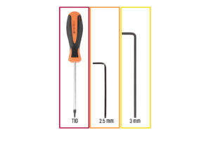
For the following steps, please prepare:
⬢
T10 screwdriver
⬢
2.5mm Allen key
⬢
3mm Allen key
Loading...
Next
Contents
Original Prusa XL Single-Tool (Semi-Assembled)
1. Introduction
2. Base & Side frame assembly
3. CoreXY & Back assembly
Tools necessary for this chapter
Torque indicator disassembly
Installing the CoreXY assembly: parts preparation
How to insert the M3nEs nuts
CoreXY assembly
Installing the CoreXY assembly
Installing the CoreXY assembly
Securing the CoreXY
Handling the printer
Torque indicator: parts preparation
Assembling the Torque indicator
Securing the CoreXY
Securing the left linear rail
Securing the right linear rail
Haribo time!
Earthing-connectors: parts preparation
Inserting the M3nEs nuts into extrusions
Grounding the Frame
Grounding the sides
Grounding the rear side
Cover-clips: parts preparation
Attaching the cover-clips
Attaching the cover-clips
XL rear panel: parts preparation
Removing the electronics casing
Attaching the XL rear panel
Attaching the XL rear panel
Installing the XL rear panel
Installing the XL rear panel
Haribo time!
Rear left: cable management
Rear left: PE cable
Rear left: connecting the cables
Rear left: securing the cables
Rear right: cable management
Rear right: connecting the cables
Rear right: connecting Wi-Fi Antenna
Installing the frame grounding
Rear right: securing the cables
Overview of electronics wiring
Rear electronics covers preparation
Rear electronics cover
Installing XL buddy box cover
Installing the extrusion covers: parts preparation
Installing front extrusion covers
Instaling rear extrusion covers
Haribo time!
Good job!
4. Heatbed & Side panels assembly
5. Nextruder & accessories assembly
6. First run
Manual changelog
Comments
Log in
to post a comment
No comments