English
Login
3D printers
Materials
Parts & Accessories
For Business
Software
3D Models
Community
Help
Courses
Blog
Company
Support
Original Prusa i3 MK2.5S
Original Prusa i3 MK2 to MK2.5S upgrade
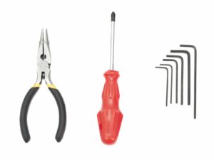
3. E-axis assembly | Tools necessary for this chapter
1. Tools necessary for this chapter
Step 1 of 66 (Chapter 3 of 7)
Contents
Comments
⬢
Needle-nose pliers for zip tie trimming.
⬢
2.5mm Allen key for M3 screws
⬢
2mm Allen key for nut alignment
⬢
1.5mm Allen key for tightening the pulley
Loading...
Next
Contents
Original Prusa i3 MK2 to MK2.5S upgrade
1. Introduction
2. Disassembly
3. E-axis assembly
Tools necessary for this chapter
Few tips before we start
Extruder-body parts preparation
Extruder-body parts preparation
Extruder-body assembly
FS-lever assembly
Steel ball assembly
Extruder motor parts preparation
Bondtech gear assembly
Bondtech gear alignment
Extruder-cover part preparation
Hotend parts preparation
Hotend assembly
Extruder assembly
X-carriage parts preparation
X-carriage assembly
Assembling the IR-sensor cable
Assembling the X-carriage
Assembling the X-carriage
IR-sensor parts preparation
IR-sensor assembly
IR-sensor assembly
Hotend fan parts preparation
Hotend fan cable adjustment
Hotend fan assembly
Hotend fan assembly
Extruder-idler parts preparation
Bearing assembly
Extruder-idler assembly
Filament alignment check
Extruder-idler mounting
Pretensioning the Extruder-idler
Print-fan-support parts preparation
Print-fan-support assembly
Fan-shroud parts preparation
Fan-shroud assembly
Print fan parts preparation
Print fan assembly
P.I.N.D.A. sensor parts preparation
P.I.N.D.A. sensor assembly
FS-cover parts preparation
FS-cover assembly
Extruder parts preparation
Extruder preparation and mounting
Extruder channels cable management
X-axis belt parts preparation
X-axis belt assembly
X-axis belt assembly
X-axis belt assembly
Tensioning the X-axis belt
Aligning the X-axis belt
Testing the X-axis belt
Trimming the X-axis belt
Nylon guide parts preparation
Nylon guide assembly
X-carriage-back parts preparation
Cable-holder assembly
X-carriage-back assembly
Mounting the X-carriage-back
X-carriage-back assembly
Textile sleeve parts preparation
Tightening the textile sleeve
Tightening the textile sleeve
Endstop-block parts preparation
Endstop-block assembly
E-axis is finished!
4. Heatbed assembly
5. Electronics
6. Preflight check
Manual changelog MK2.5S
Comments
Log in
to post a comment
No comments