English
Login
3D printers
Materials
Parts & Accessories
For Business
Software
3D Models
Community
Help
Courses
Blog
Company
Support
Original Prusa XL
Original Prusa XL Single-Tool (Semi-Assembled) (1.07)
4. Heatbed & Side panels assembly | Tools necessary for this chapter
1. Tools necessary for this chapter
Step 1 of 22 (Chapter 4 of 7)
Contents
Comments
⬢
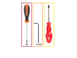
For this chapter, please prepare:
⬢
T10 screwdriver
⬢
2.5mm Allen key
⬢
Phillips PH2 screwdriver
Loading...
Next
Contents
Original Prusa XL Single-Tool (Semi-Assembled)
1. Introduction
2. Base & Side frame assembly
3. CoreXY & Back assembly
4. Heatbed & Side panels assembly
Tools necessary for this chapter
Side panels preparation
Left side panel assembly (part 1)
Left side panel assembly (part 2)
Right side panel assembly
Haribo time!
Heatbed assembly versions
Heatbed assembly preparation
Heatbed terminals preparation
Connecting the Heatbed cables
Assembling the Heatbed
Preparing the heatbed cable screws
Fixing the heatbed cables in place
Removing linear rail stoppers
Installing the Heatbed
Attaching the Heatbed
Preparing the Z-Axis bearing housing
Installing the Z-Axis bearing housing
Preparing the Heatbed screws
Fixing the X-axis side parts in place
Haribo time!
Good job!
5. Nextruder & accessories assembly
6. First run
Manual changelog
Comments
Log in
to post a comment
No comments