English
Login
3D printers
Materials
Parts & Accessories
For Business
Software
3D Models
Community
Help
Courses
Blog
Company
Support
Original Prusa i3 MK3S
Original Prusa i3 MK3S kit assembly (v3.15)
7. Heatbed & PSU assembly (Black PSU) | Tools necessary for this chapter
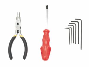
1. Tools necessary for this chapter
Step 1 of 35 (Chapter 7 of 11)
Contents
Comments
⬢
Needle-nose pliers for the heatbed assembly
⬢
2.5mm Allen key for M3 screws
⬢
2mm Allen key for heatbed alignment
Loading...
Next
Contents
Original Prusa i3 MK3S kit assembly
1. Introduction
2. Y-axis assembly
3. X-axis assembly
4. Z-axis assembly
5. E-axis assembly
6. LCD assembly
7. Heatbed & PSU assembly (Black PSU)
Tools necessary for this chapter
Heatbed cable assembly (part 1)
Heatbed cable assembly (part 2)
Heatbed cable assembly (part 3)
New heatbed cable cover design
Preparing the heatbed (new design)
Preparing the heatbed-cable-cover
Mounting the heatbed-cable-cover
Mounting the heatbed-cable-cover
Proper cable management
Wrapping the heatbed cables
Securing the sleeve in place
Finalizing the wrap
Preparing the heatbed (old design)
Preparing the heatbed-cable-cover
Mounting the heatbed-cable-cover
Proper cable management
Wrapping the heatbed cables
Securing the sleeve in place
Finalizing the wrap
Preparing the heatbed screws and spacers
Mounting the heatbed (part 1)
Mounting the heatbed (part 2)
Mounting the heatbed (part 3)
Mounting the heatbed (part 4)
Checking the hotend cables
Preparing the PSU parts
Assembling the PSU
Assembling the PSU
Connecting the power cables (CRITICAL)
Connecting the power cables
Connecting the power cables
Power panic and PSU cover
Haribo time!
Heatbed and PSU are done!
7. Heatbed & PSU assembly (Silver PSU)
8. Electronics assembly
9. Preflight check
Manual changelog
Comments
Log in
to post a comment
Wahngrok
•
The screwdriver is also needed for the connection of the power cables to the PSU.
Reply
NightmareOn
•
aww 4 more steps than the old PSU.
Reply