Italiano
Login
Stampanti 3D
Materiali
Componenti e accessori
Per le aziende
Software
Modelli 3D
Community
Aiuto
Corsi
Blog
Azienda
Supporto
Original Prusa i3 MK2S
Kit da assemblare Original Prusa i3 MK2S
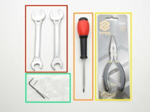
4. Z-axis assembly | Ottenere gli attrezzi necessari
1. Ottenere gli attrezzi necessari
Passo 1 di 27 (Capitolo 4 di 9)
Contenuti
Commenti
⬢
Chiavi inglesi 13/17mm
⬢
cacciavite a testa piatta 3.6mm
⬢
Pinza a becchi larghi
⬢
Chiave a brugola da 2.5 e 1.5 mm
Loading...
Successivo
Contenuti
Kit da assemblare Original Prusa i3 MK2S
1. Introduzione
2. Y-axis assembly
3. Assemblaggio asse X
4. Assemblaggio asse Z
Ottenere gli attrezzi necessari
Avvita i supporti inferiori Z alla cornice
Posizionare i motori Z
Posizionare i dadi trapezoidali del motore
Identificare la lunghezza delle barre
Assemblaggio dell'asse X
Sistemazione cavi
Assemblaggio dell'asse Y
Assemblare la cinghia asse X, parte 2
Guida alla cinghia del carrello dell'Asse X
Allentare il motore
Stringere la cinghia asse X, parte 2
VIDEO per i passi 16-24
Tutto fatto!
Assembling the Y-axis
Assembling the X-axis belt, part 1
Assembling the X-axis belt, part 2
The X-axis belt idler guide
The X-axis belt carriage guide
The X-axis belt motor guide
Loosening the motor
Tightening the X-axis belt, part 1
Tightening the X-axis belt, part 2
Tensioning the belt
VIDEO for steps 16-24
Adjusting tension screws
All done!
5. Assemblaggio Estrusore
6. Assemblaggio LCD
7. Assemblaggio Alimentatore & Piano riscaldato
8. Assemblaggio dell'elettronica
9. Controllo finale
Commenti
Accedi
per inviare un commento
Nessun commento