Italiano
Login
Stampanti 3D
Materiali
Componenti e accessori
Per le aziende
Software
Modelli 3D
Community
Aiuto
Corsi
Blog
Azienda
Supporto
Original Prusa XL
Original Prusa XL a strumento singolo (Semi-assemblata) (1.07)
4. Montaggio del piano riscaldato e dei pannelli laterali. | Attrezzi necessari per questo capitolo
1. Attrezzi necessari per questo capitolo
Passo 1 di 22 (Capitolo 4 di 7)
Contenuti
Commenti
⬢
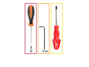
Per questo capitolo prepara:
⬢
Cacciavite T10
⬢
Chiave a brugola da 2.5mm
⬢
Cacciavite a stella PH2
Loading...
Successivo
Contenuti
Original Prusa XL a strumento singolo (Semi-assemblata)
1. Introduzione
2. Montaggio della base e del telaio laterale
3. Assemblaggio Core XY & posteriore
4. Montaggio del piano riscaldato e dei pannelli laterali.
Attrezzi necessari per questo capitolo
Preparazione dei pannelli laterali
Montaggio del pannello laterale sinistro (parte 1)
Montaggio del pannello laterale sinistro (parte 2)
Gruppo del pannello laterale destro
È l'ora delle Haribo!
Heatbed assembly versions
Preparazione del montaggio del piano riscaldato
Preparazione dei terminali del piano riscaldato
Collegamento dei cavi del piano riscaldato
Assemblaggio del piano riscaldato
Preparing the heatbed cable screws
Fissare i cavi del piano riscaldato in posizione
Rimozione dei tappi della guida lineare
Installare il piano riscaldato
Montaggio del piano riscaldato
Preparazione dell'alloggiamento del cuscinetto dell'asse Z
Installazione dell'alloggiamento del cuscinetto dell'asse Z
Preparazione delle viti del piano riscaldato
Fissare in posizione le parti laterali dell'asse X
È l'ora delle Haribo!
Ottimo lavoro!
5. Montaggio Nextruder e accessori
6. Primo avvio
Registro modifiche del manuale
Commenti
Accedi
per inviare un commento
Nessun commento