日本語
Login
3Dプリンター
マテリアル
部品 & アクセサリー
法人向け
ソフトウェア
3Dモデル
コミュニティ
ヘルプ
コース一覧
ブログ
会社概要
サポート
Original Prusa i3 MK3
Original Prusa i3 MK3キット組立て
3. X-axis assembly | この章に必要な道具
1. この章に必要な道具
ステップ 1 / 13 (章 4 / 14)
内容
コメント
⬢
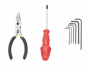
結束バンドの切断に必要なラジオペンチ
⬢
M3 ネジ 向けの 2.5mm 六角レンチ
⬢
ナット調整用の2mm六角レンチ
Loading...
次
内容
Original Prusa i3 MK3キット組立て
1. はじめに
Introduction
2. Y軸の組み立て
3. X軸の組み立て
この章に必要な道具
X軸: X エンドアイドラー と モーターホルダー
X軸: リニアベアリングを取り付ける
X-end-motor: tensioner assembly
X-end-idler: ベアリングの組み立て
X軸: スムーズロッド の組み立て準備
X軸: 組み立て
X軸 モータープーリー の組み立て (パート 1)
X軸 モータープーリー の組み立て (パート 2)
X軸: モーターの組み立て
X-carriage preparation
X-carriage: assembly
X軸の完成!
4. Z軸 の組み立て
5. E軸の組み立て (スパイラルチューブ)
5. E軸の組み立て (ケーブルスリーブ)
6. LCD の組み立て
7. ヒートベッドと電源ユニットの組み立て (スパイラルチューブ)
7. ヒートベッドと電源ユニットの組み立て (ケーブルスリーブ)
8. 電子部品の組み立て (B3/R2 デザイン)
8. 電子部品の組み立て (B7/R2 デザイン)
9. プリフライト確認
マニュアルの変更ログ
コメント
ログイン
してコメントを投稿する
コメントなし