EN
  • Čeština
  • Español
  • Italiano
  • Deutsch
  • Polski
  • Français
  • 日本語
Login

2. MMU1 disassembly

2. MMU1 disassembly
Relevant for:
Last updated 4 years ago
2. MMU1 disassembly
 Difficulty
Moderate
 Steps
7
 Available languages
CSPLESDEITFRJA
Preparing the printer
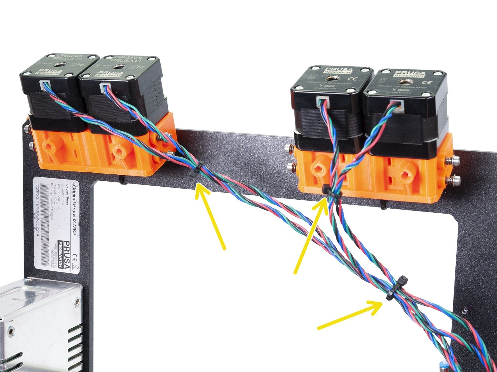
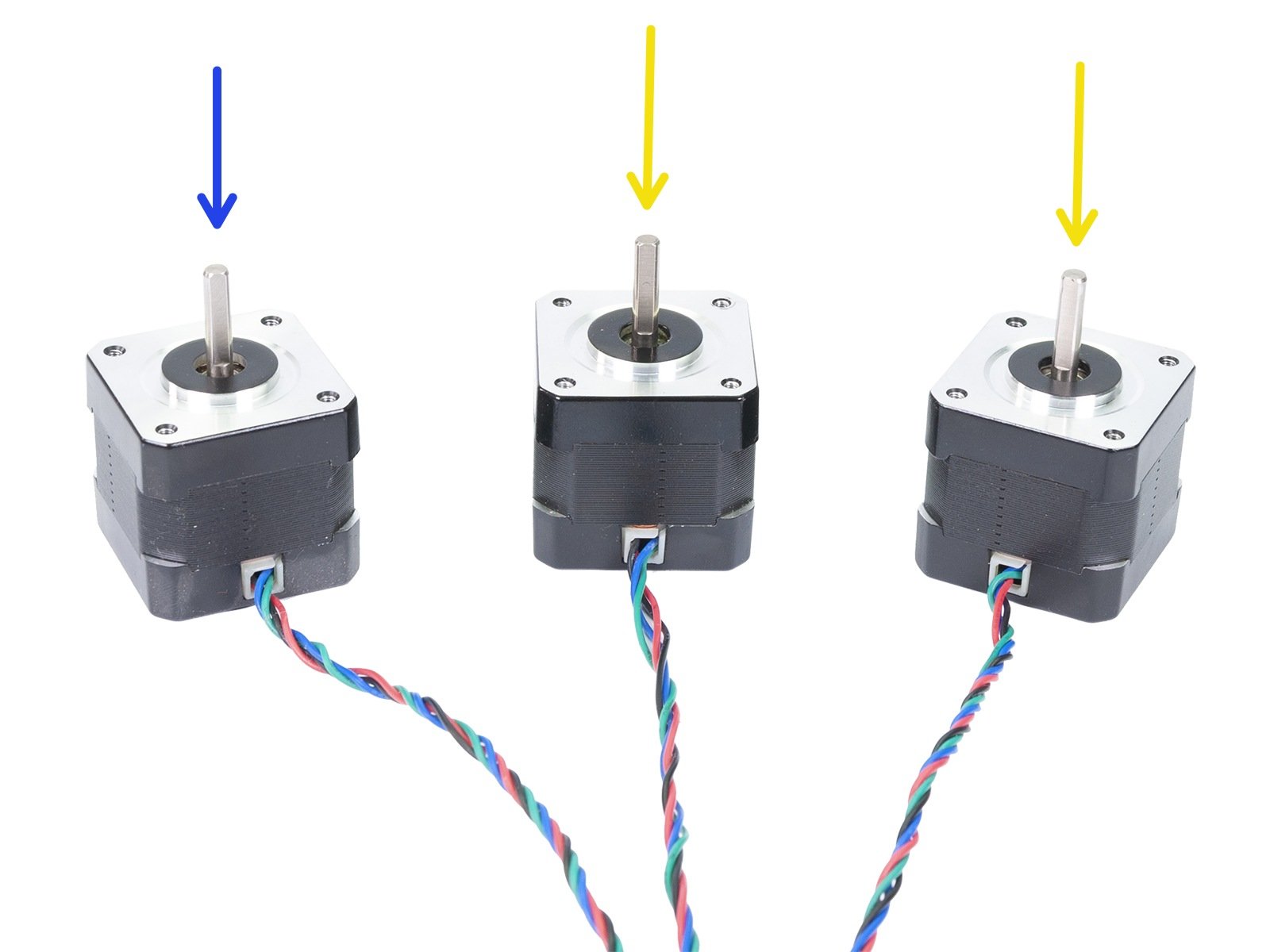
Make sure the filament is unloaded from the hotend and removed from the extruders on the frame.
Ensure the printer is not connected to the power outlet, otherwise, there is a risk of damage to the electronics!
Getting the necessary tools
For the MMU1 disassembly you will need:
Needle-nose pliers (1x)
Allen key 2.5 mm
Allen key 1.5 mm
Tools can be used from the MMU2S upgrade kit, but don't unpack the entire kit, so you won't accidentally mix parts.
No soldering is required.
No wire crimping is required.
MMU1 disassembly (part 1)
Ensure again the printer is not connected to the power outlet, otherwise, there is a risk of damage to the electronics!
Let's start on the backside of the printer above the RAMBo casing (LCD is facing away from you).
Release the M3 screw on the case using the 2.5 Allen key. Remove the cover to access the cables inside.
Note your case can be smaller, but the procedure is the same.
Carefully take all the cables out and unplug the connectors.
Use both holes in the case to pull the cables out. Proceed with caution, don't damage the connectors.
MMU1 disassembly (part 2)
In case you intend to use this printer for the MMU2S upgrade, please use Allen key to release both M3 screws.
Remove the case with the board completely. Both parts won't be used in the future.
MMU1 disassembly (part 3)
Using pliers cut the zip ties and untangle the cables. Be careful as you might cut the wires.
Turn the printer around.
Using 8mm wrench release the QSM fittings with the white PTFE tubes on both extruders (together 4 tubes).
Cut the zip ties on both extruders and remove them from the printer's frame.
MMU1 disassembly (part 4)
Take the first extruder and release all eight M3 screws.
Remove the printed part from the motors.
BEFORE YOU PROCEED READ THIS! We are about to release the lock screw on the pulley. Proceed with extreme caution as you can strip the screw!!! If possible apply some grease first.
Very carefully release the lock screws, be careful as you might strip the screw's head or thread.
Remove the pulleys and put them away, so you won't mix them with the new ones from the MMU2S kit.
Repeat this procedure for the second extruder. Together you need 3 motors without the pulley.
Use one motor in the MK2.5S assembly for the Extruder.
Use the remaining two motors for the MMU2S unit.
Was this guide helpful?

Comments

Still have questions?

Still have questions?

If you have a question about something that isn't covered here, check out our additional resources.
And if that doesn't do the trick, you can send an inquiry to [email protected] or through the button below.

Contact us