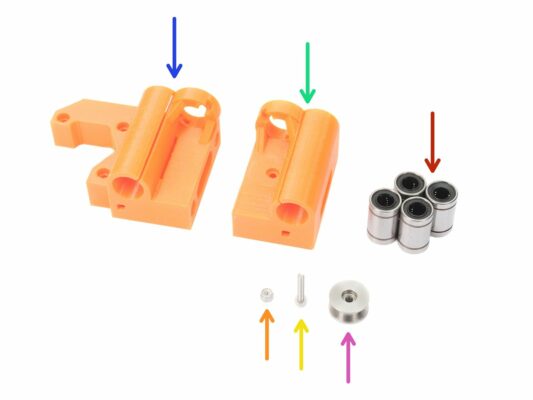
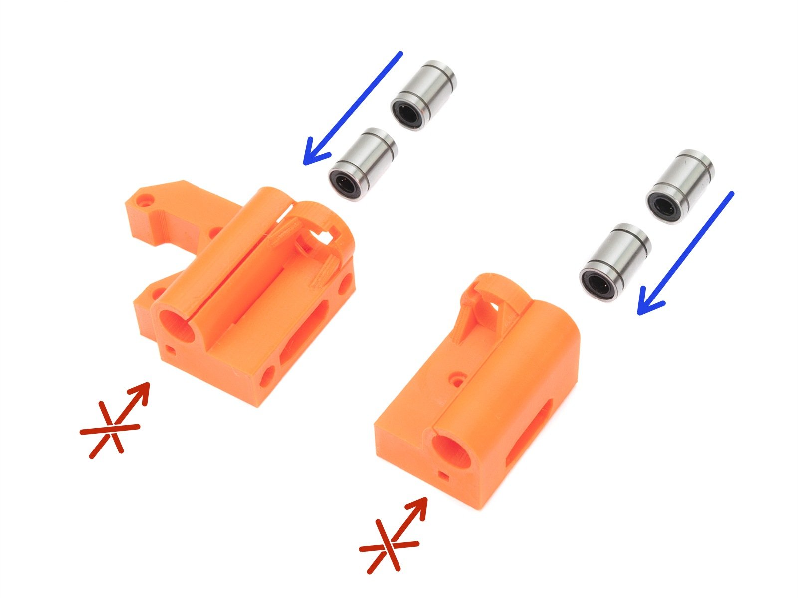
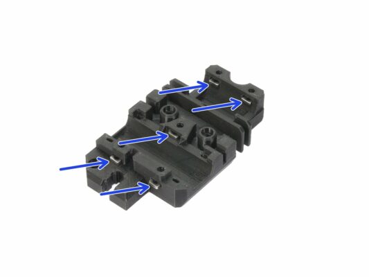
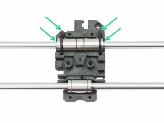
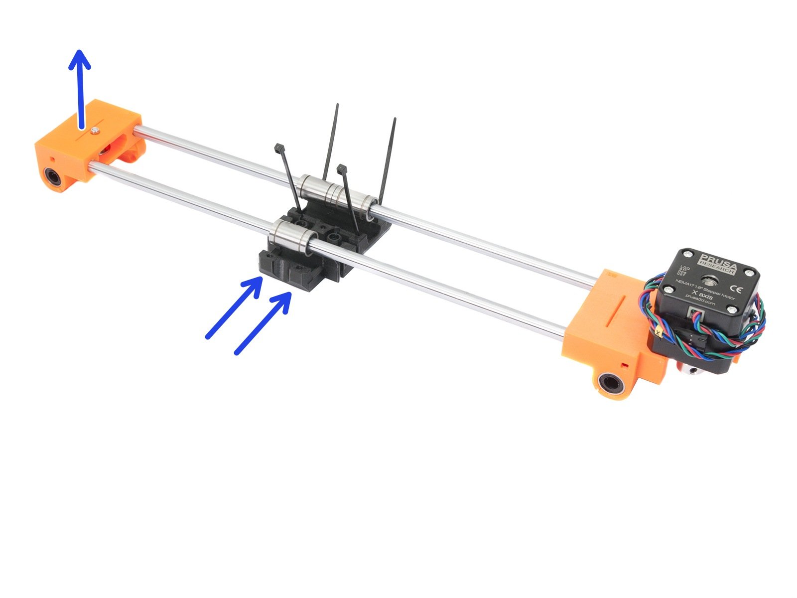
⬢Insert LM8UU linear bearings into the printed parts (X-end-motor and X-end-idler) as shown in the picture.
DON'T TRY TO PUSH the bearings from the other side. There is a rim (smaller diameter of the hole).
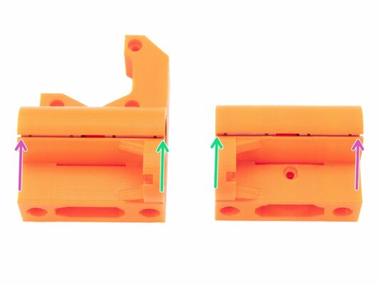
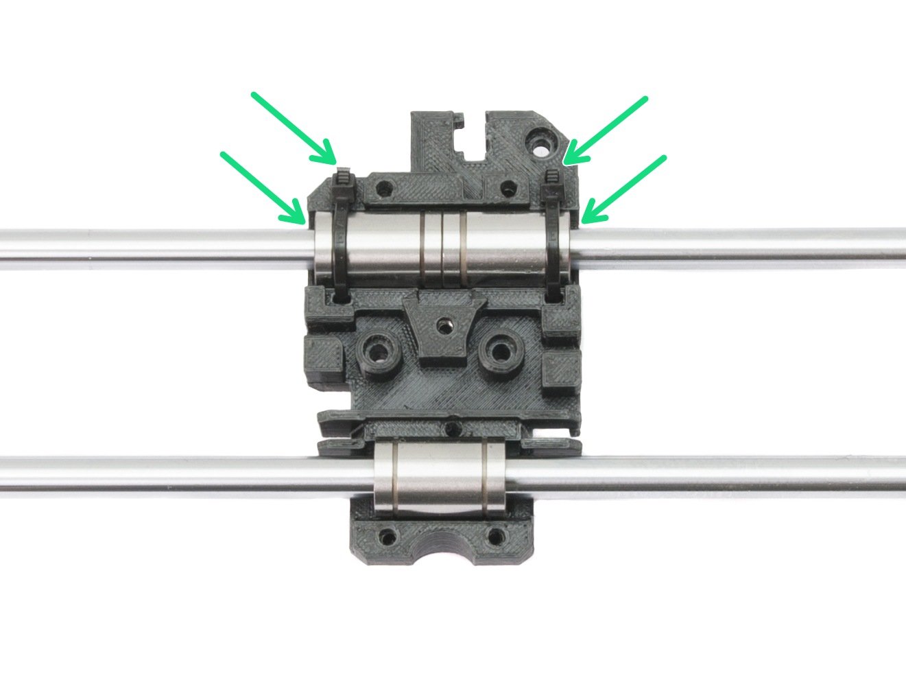
⬢First pair of bearings should be in line with the top surface on both X-ends.
⬢Second pair of bearings should be seated on the rim (close to the lower surface) on both X-ends.
You can press the bearings against the flat surface for easier insertion.
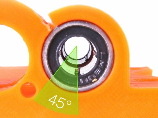
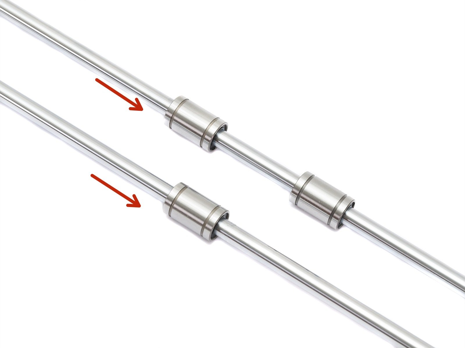
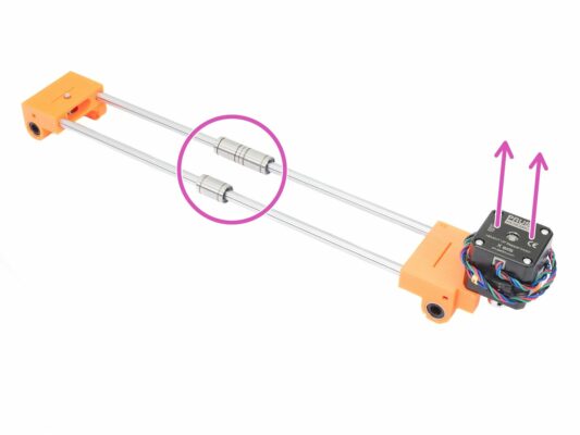
Place two bearings in a way that the inner balls of the second bearing are rotated 45° compared to the first. This way you will achieve greater contact with the smooth rod. See the third picture for more details.
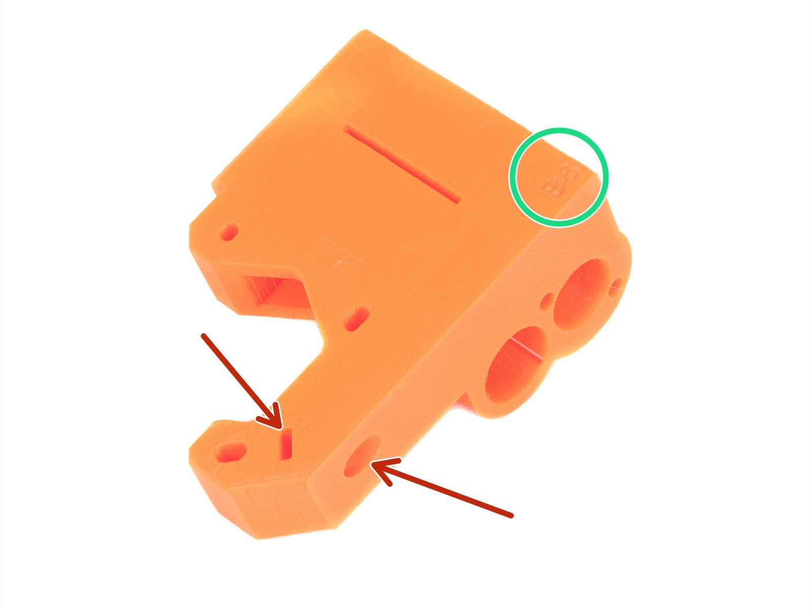
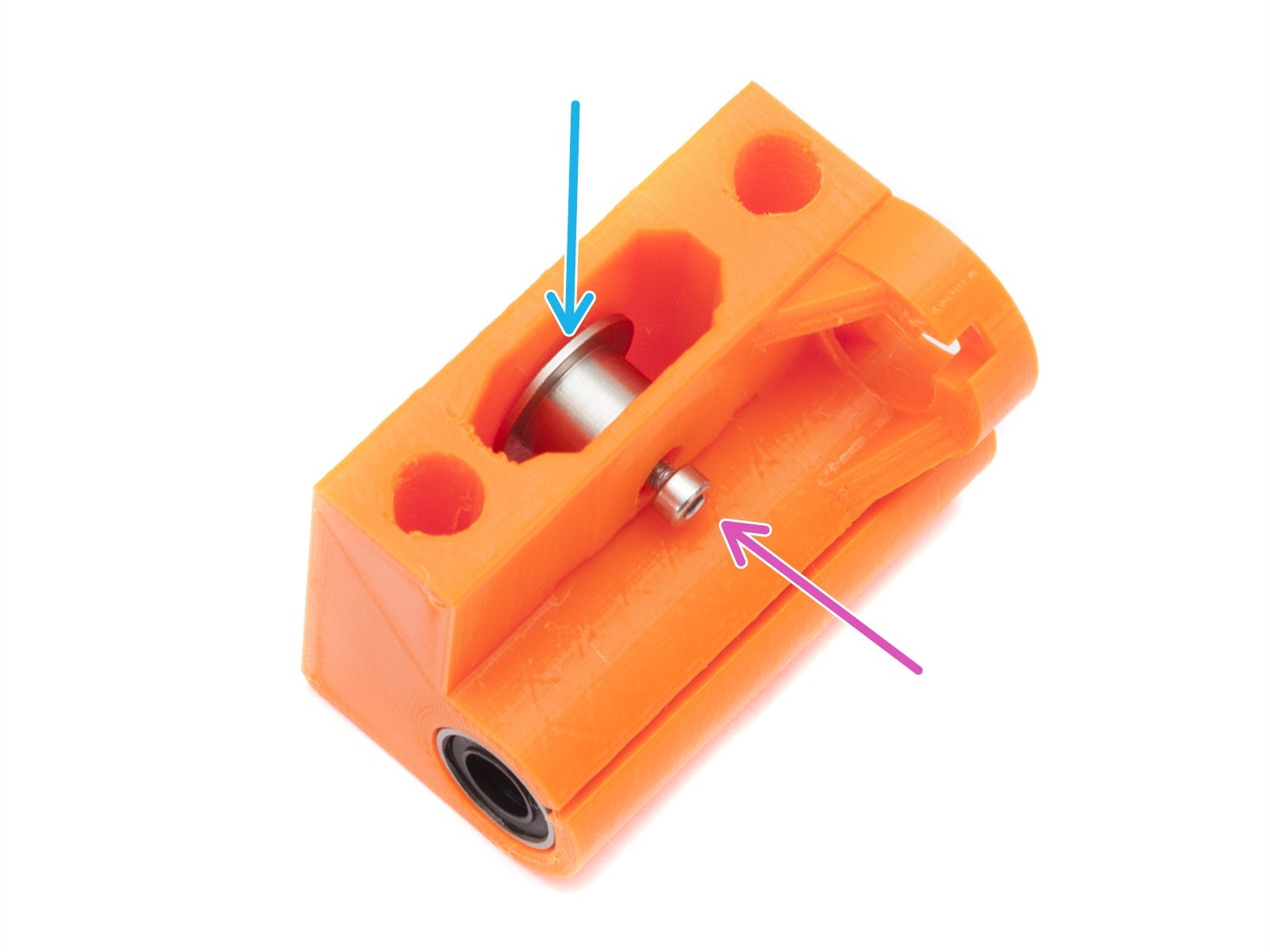
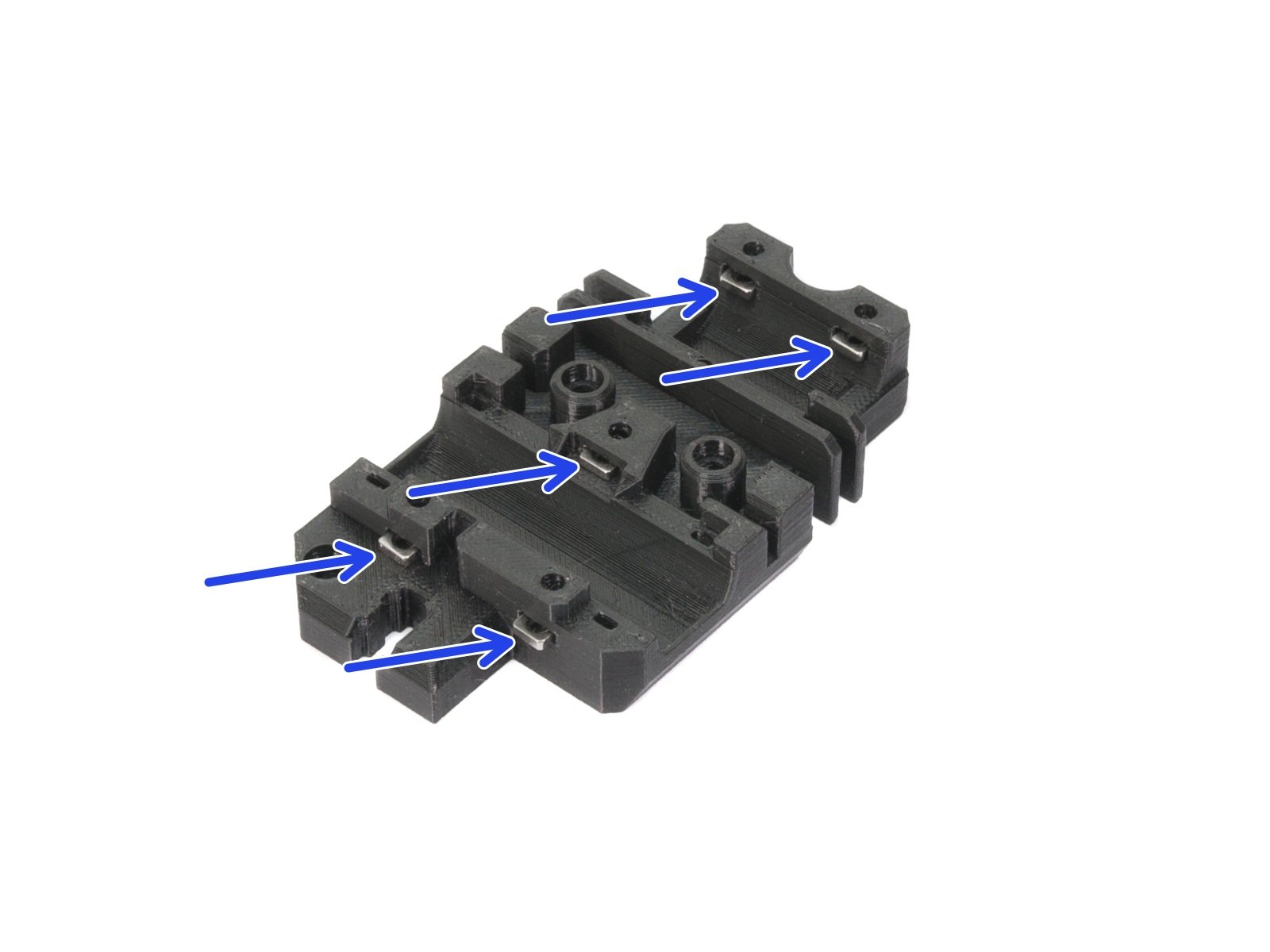
Check your X-end-motor printed part for following holes. If they are present, please follow this step, otherwise skip to the next one.
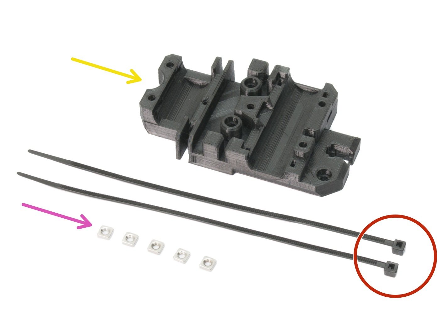
⬢You can also check the version of the printed X-end-motor, this step is valid for B6 and higher.
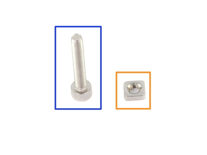
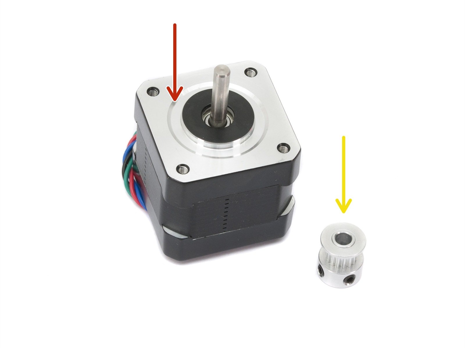
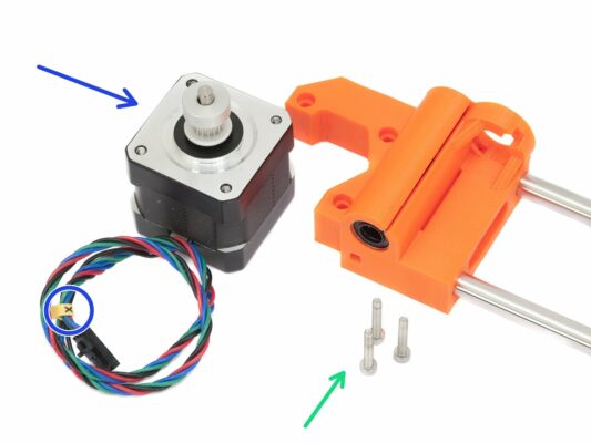
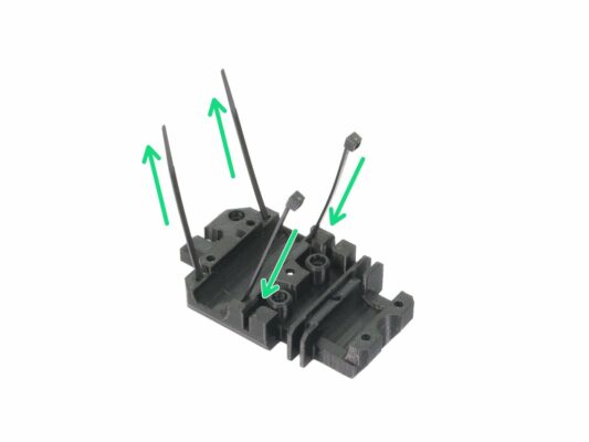
⬢Please prepare following:
⬢M3nS nut (1x)
⬢M3x18 screw (1x)
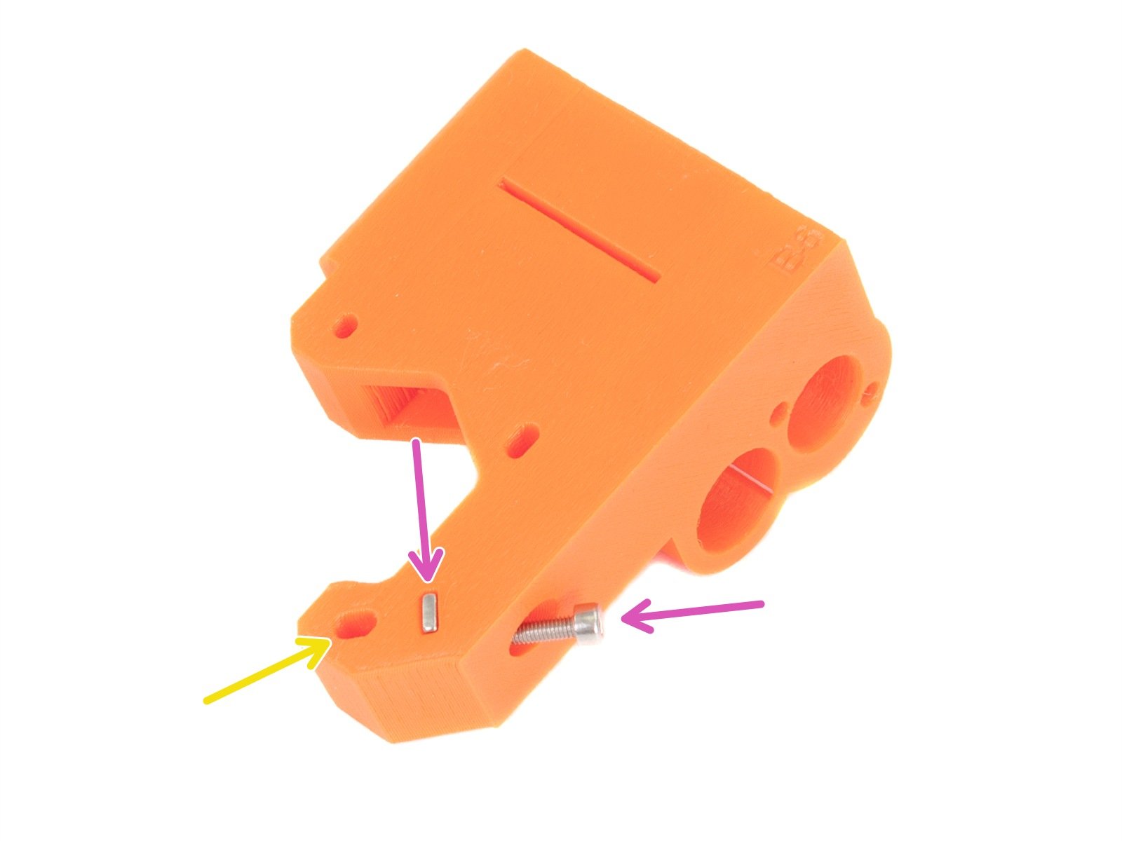
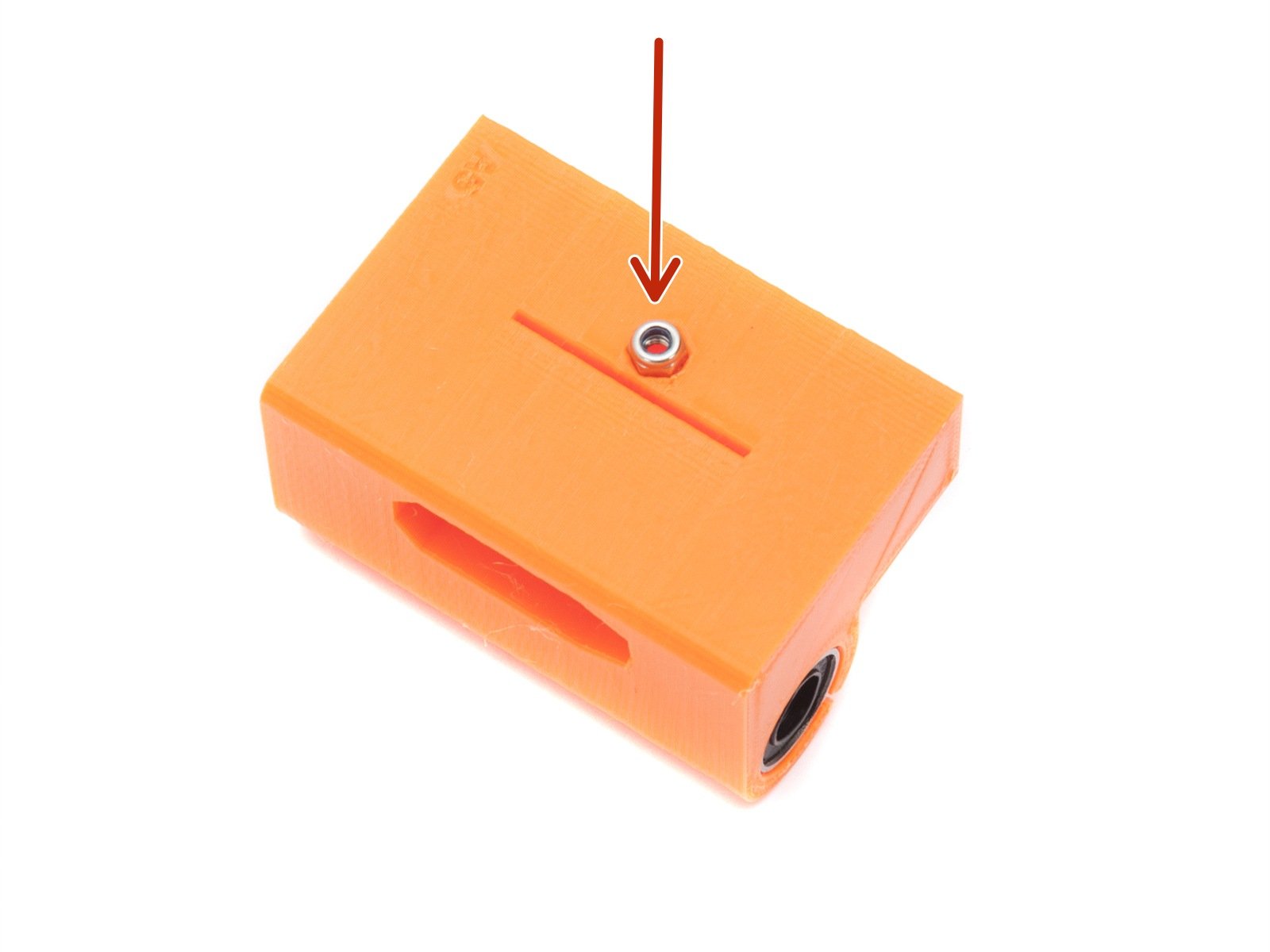
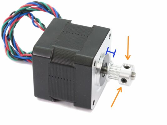
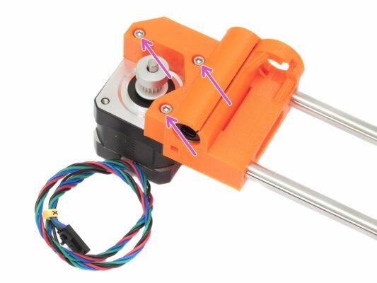
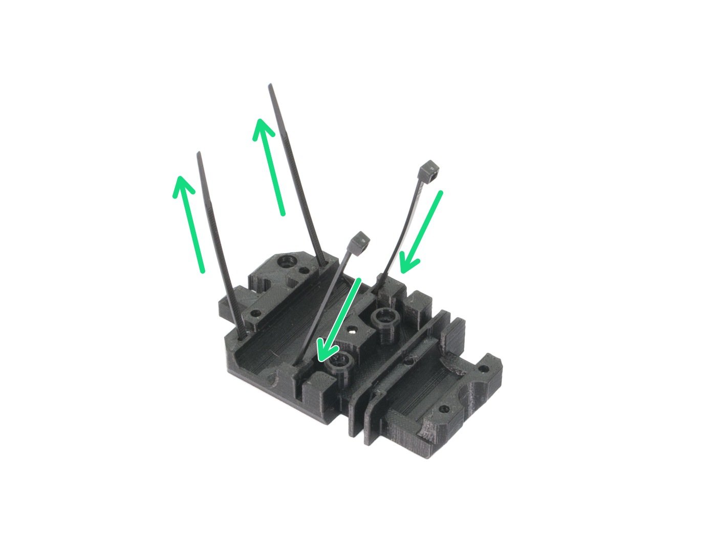
⬢Insert nut and screw in the holes. For now, we need the screw just to hold in place. Tighten the screw, until its head almost reaches the surface of the printed part. We will adjust the final position later.
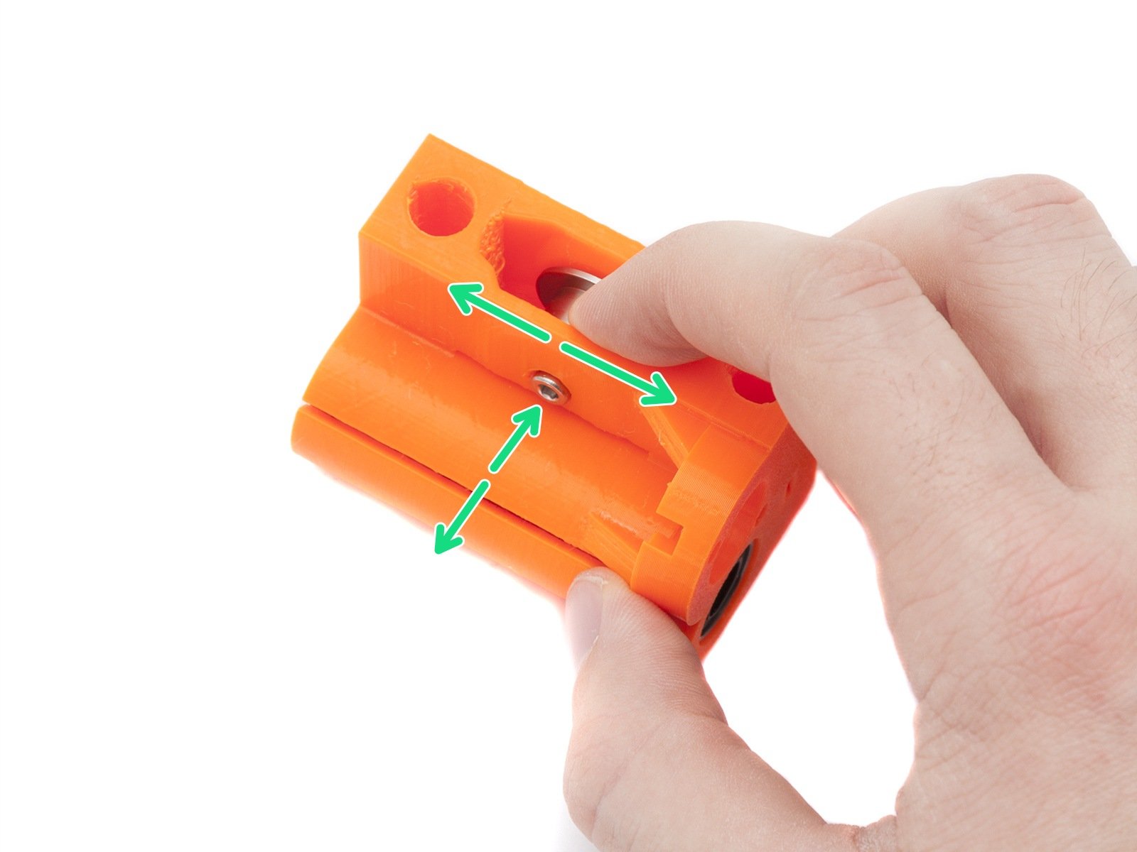
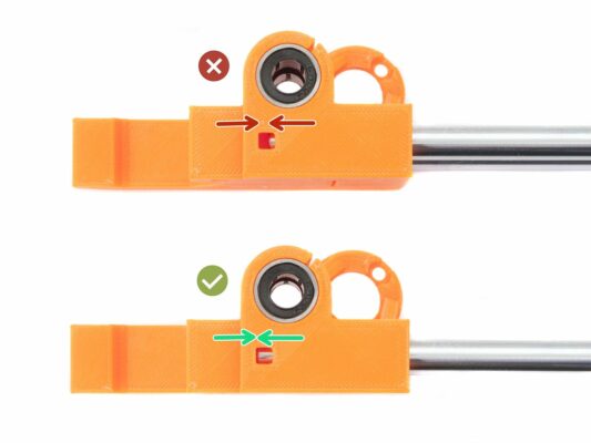
⬢Make sure the M3x18 screw is not visible in the marked hole (see the last picture) as it will block other screw in future step. If you can see the screw in the hole now, please release it slightly.
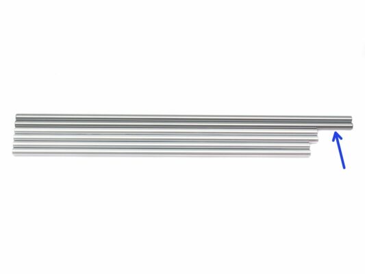
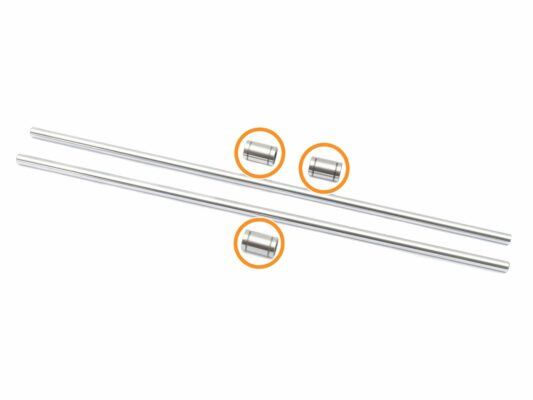
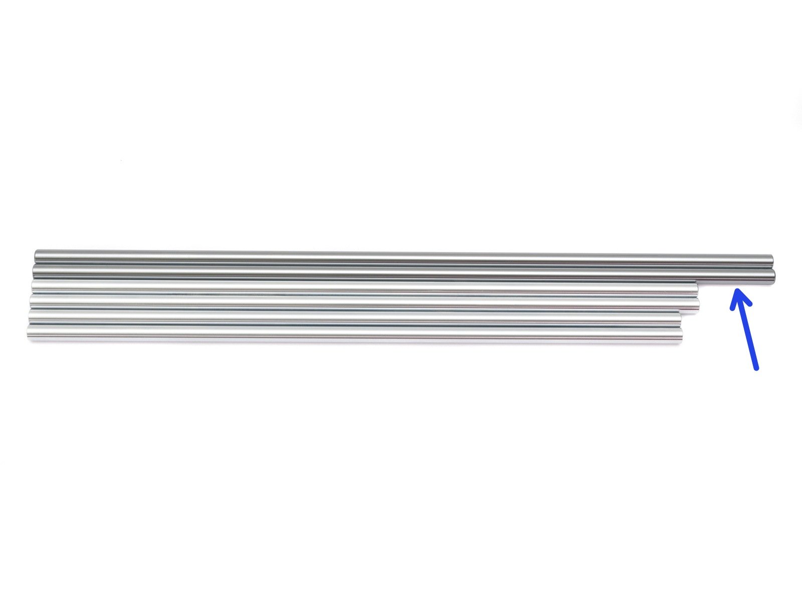
⬢Take remaining smooth rods and compare their length. For X-axis you need longest rods (370 mm).
⬢Linear bearing (3x)
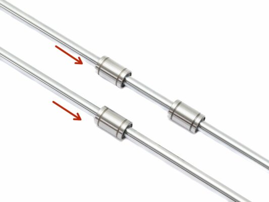
NOW, PLEASE BE VERY CAREFUL! Gently insert the rod straight into the bearings, do not apply too much force and do not tilt the rod!
In case you manage to push out balls from the bearings, please count them. One or two balls are ok, if there are more of them, please consider ordering new bearings.
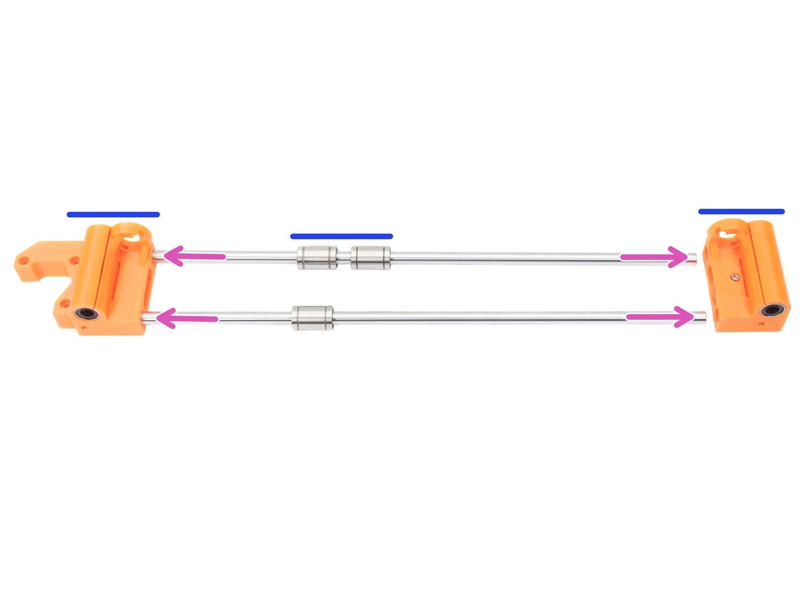
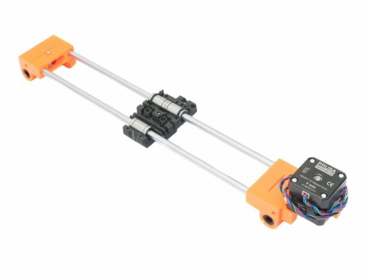
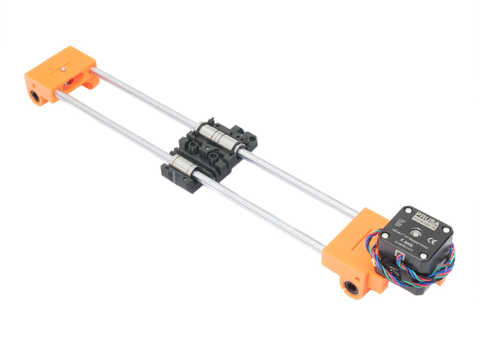
⬢Insert the rods with bearings fully into the printed parts.
Insert the rods very carefully. Do not tilt the rods too much.
⬢Ensure the correct orientation of the parts and rods.
⬢There is a special opening in the bottom of both X-ends. Check if you pressed the smooth rod all the way in. The second (upper) rod doesn't have these openings.
If you have a question about something that isn't covered here, check out our additional resources. And if that doesn't do the trick, you can send an inquiry to [email protected] or through the button below.