This guide describes how to install the Prusa USS Drybox on the Prusa XL printer.
The XL uses a multi-toolhead system, and each toolhead requires a different PTFE length and mounting position for the Drybox.
This guide covers Drybox mounting, toolhead-specific PTFE routing, and connection to the filament path.
Before starting, make sure the Drybox is fully assembled and loaded with filament. If not, follow the First setup and filament loading (USS Drybox) article.
PTFE tube preparation
For Prusa XL, the PTFE tube length depends on the selected toolhead:
- Toolhead 1: 23 cm
- Toolhead 2: 35 cm
- Toolhead 3: 28 cm
- Toolhead 4: 23 cm
- Toolhead 5: 35 cm
Ensure a clean, straight cut to avoid filament friction or misalignment.
You will need:
- M4 Allen key
- Pliers
- 2x M4x6 screws for each drybox
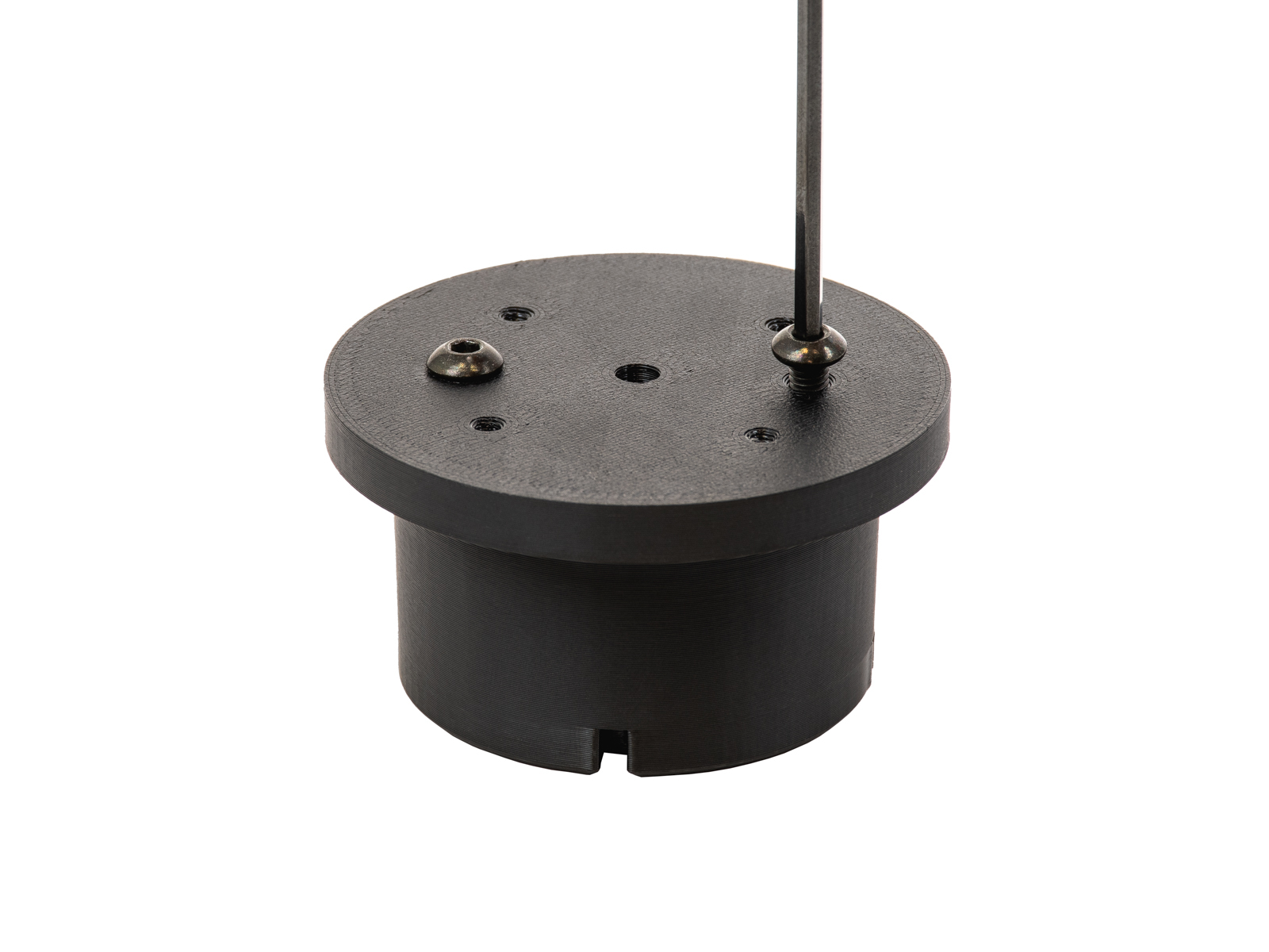
- Prepare the number of pucks you will need (1, 2, or 5) by placing two M4x6 screws on their flat part.
 |  |
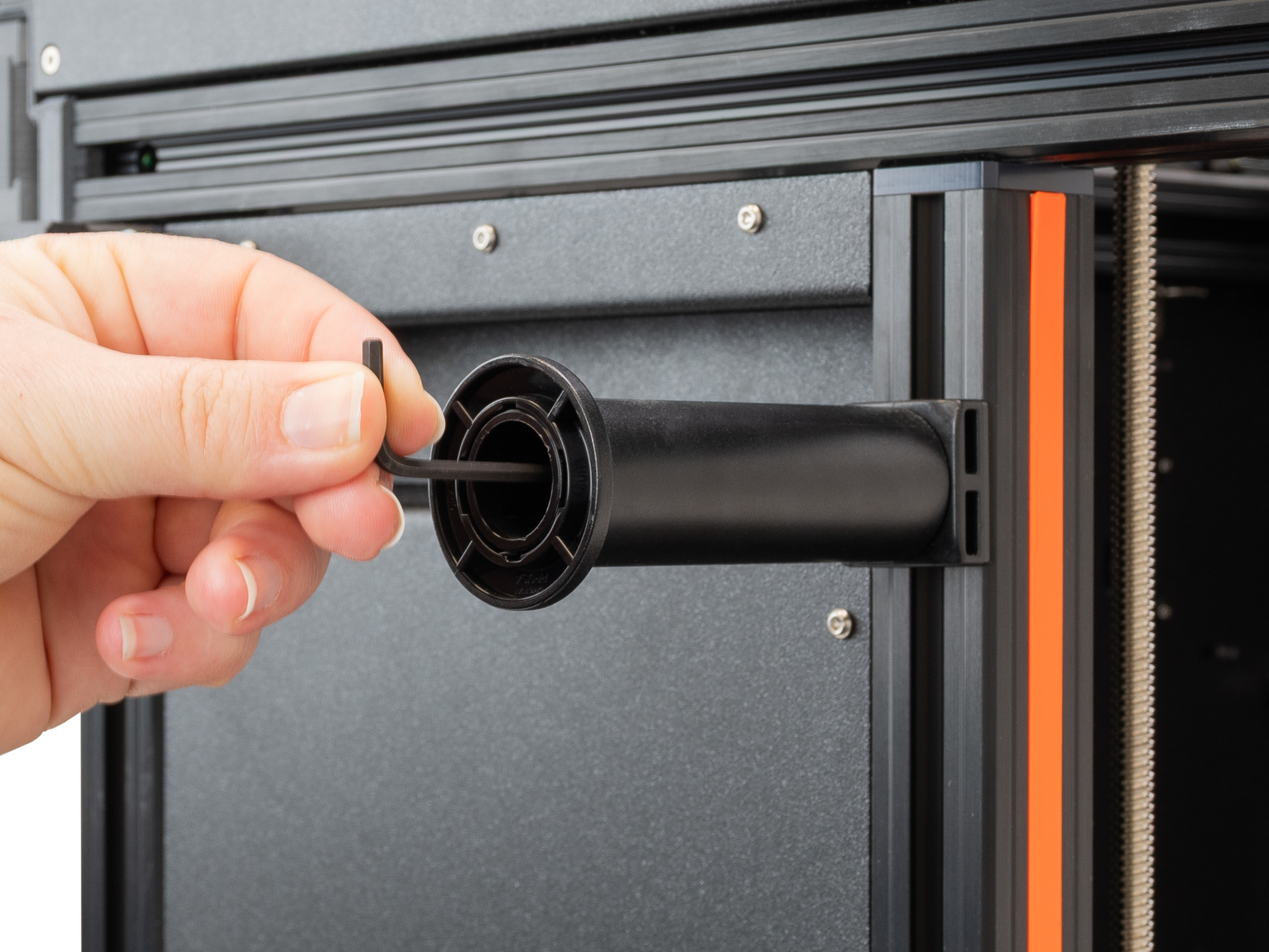
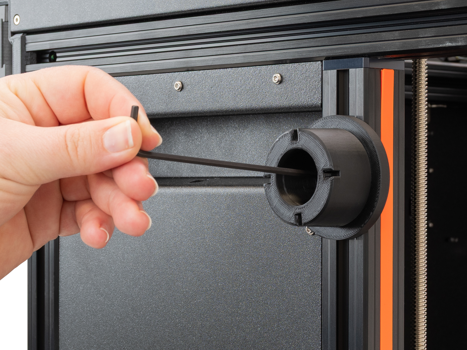
- Unscrew the spoolholders with an M4 Allen key.
 |  |
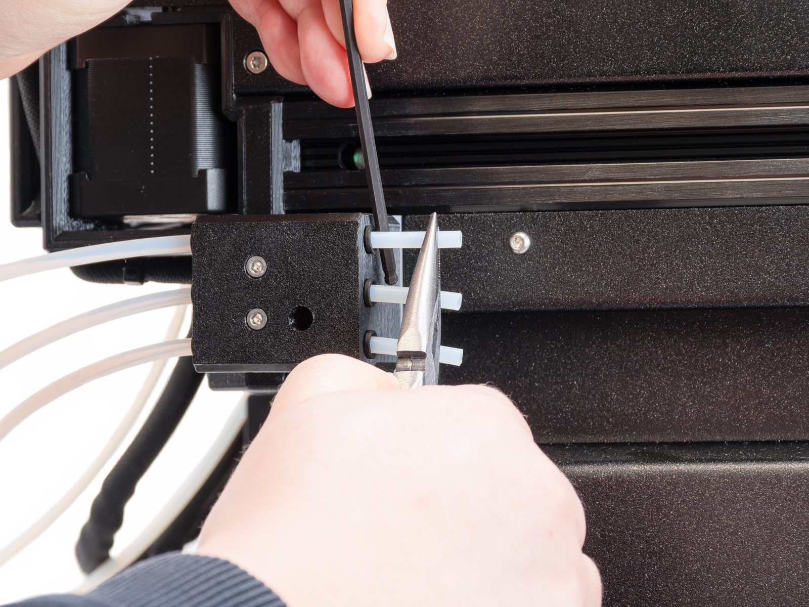
- Remove the PTFE tube from the side filament sensor.
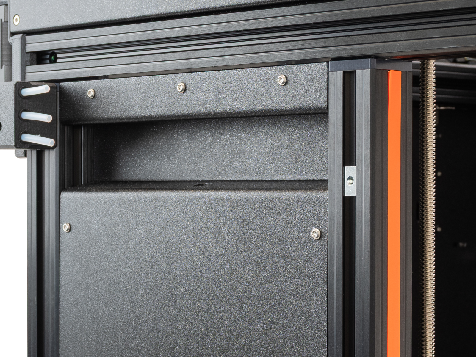
- Place the puck in a way that the previously placed screws are inside the extrusion groove. Screw a puck to each place where a spoolholder was using the M4x12 screw that was previously holding the XL spoolholder.
- Place the drybox on the puck. We recommend using the positions below for the five positions. Lock it with the removable spoolholder.
 | 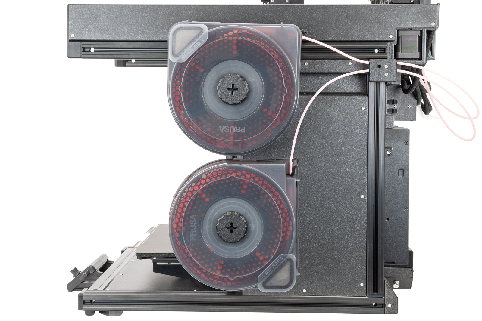 |
- Load the filament through the side filament sensor, and insert the drybox PTFE tube in the side sensor case.
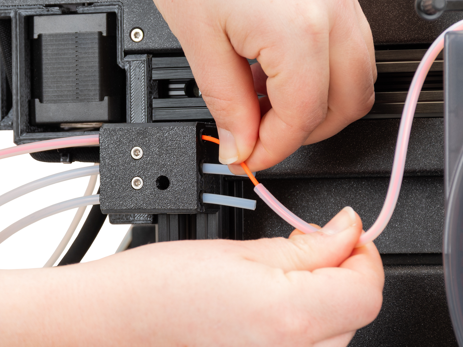 | 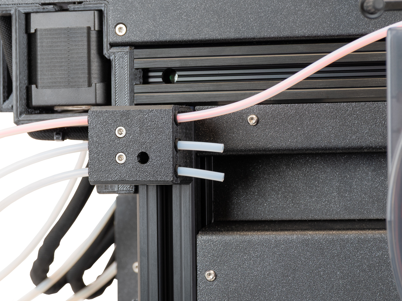 |
この記事は役に立ちましたか?
この操作は登録ユーザーのみが利用できます。ログインしてください。