La función Input Shaper de la Prusa CORE One, y en las Original Prusa MK4/S, MK3.9/S se puede calibrar usando un acelerómetro opcional.
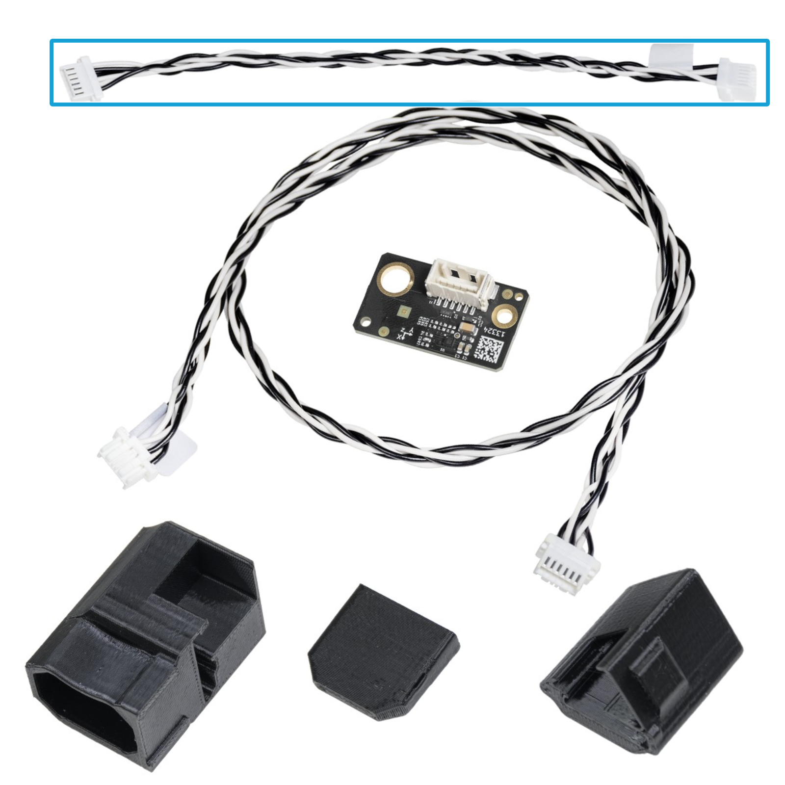
El conjunto del acelerómetro consiste en una pequeña placa de circuito impreso encerrada en una cubierta impresa, que se conecta a la impresora. Ten en cuenta que el uso del acelerómetro requiere el desmontaje parcial de la impresora.
El input shaper viene precalibrado de fábrica, por lo que esta calibración suele ser innecesaria en una impresora de stock. Sin embargo, si has hecho alguna modificación en el hardware de la impresora, puede ser beneficioso recalibrar los ajustes utilizando el acelerómetro.
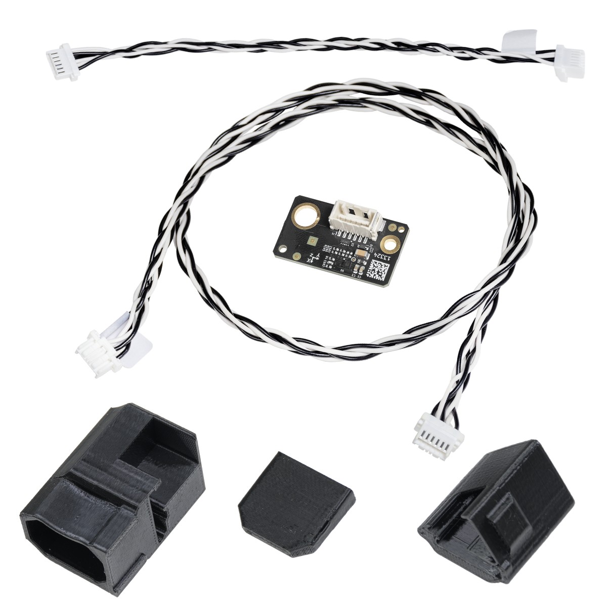
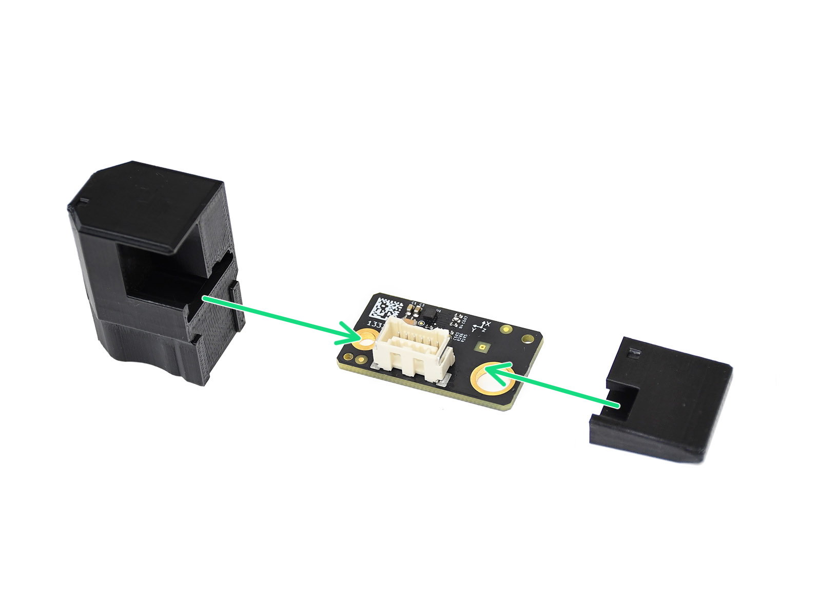 | 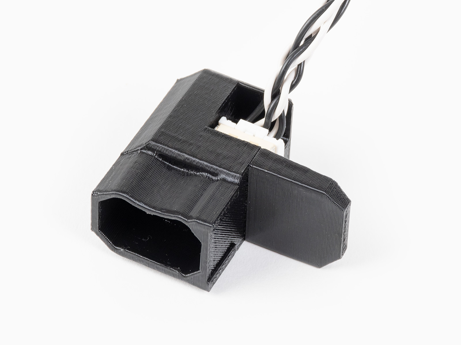 |
Prusa CORE One
Retira temporalmente la cubierta de la placa Wi-Fi, aflojando su tornillo M3x12.
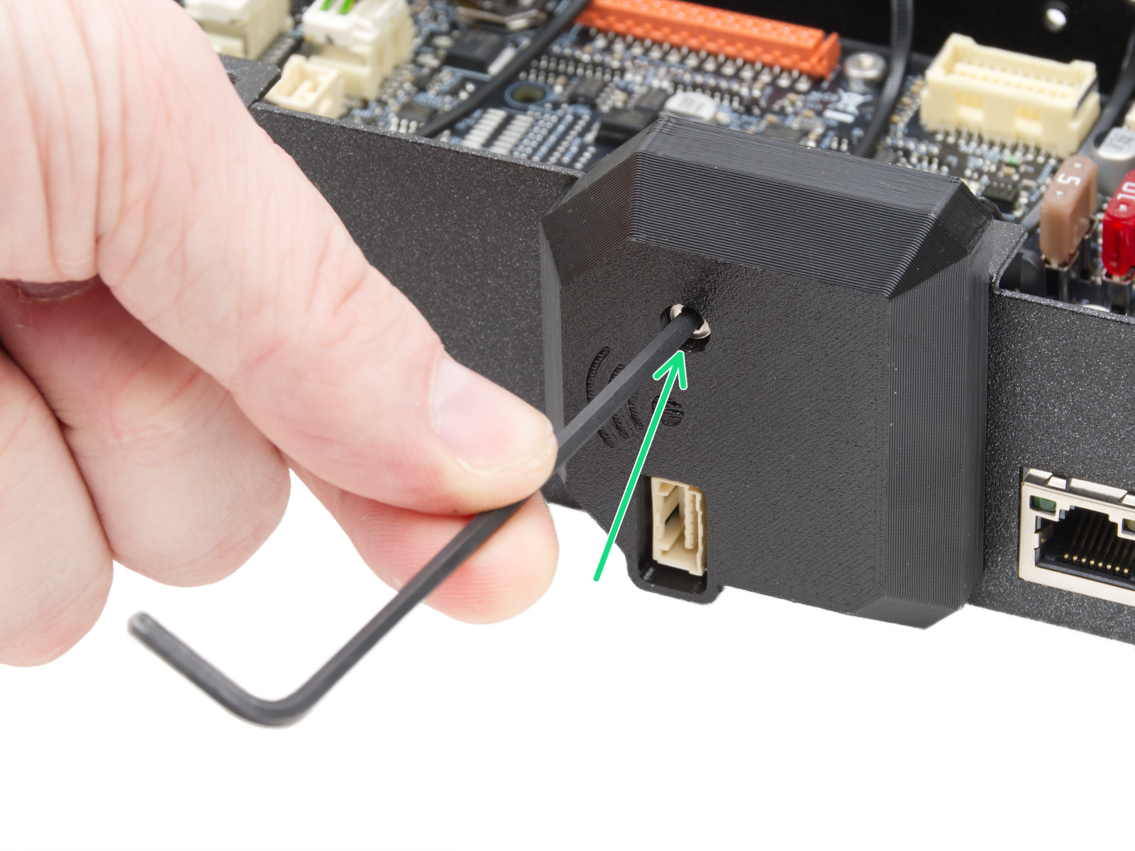
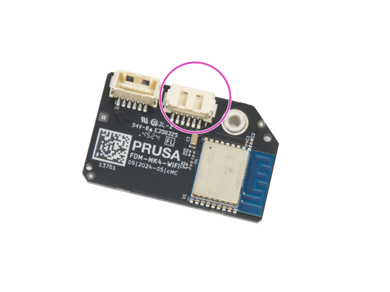
Conecta el cable de puente entre el conector de la xBuddy y el conector del módulo Wi-Fi.
 |  |
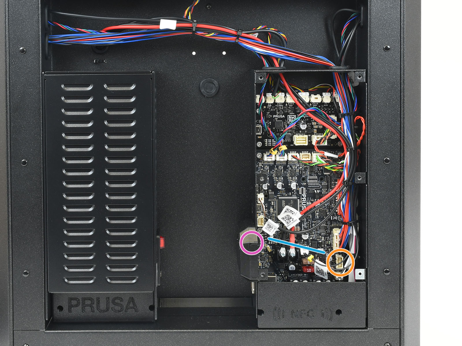
Retira la tapa circular de la parte posterior. A continuación, pasa el cable del acelerómetro por el orificio.
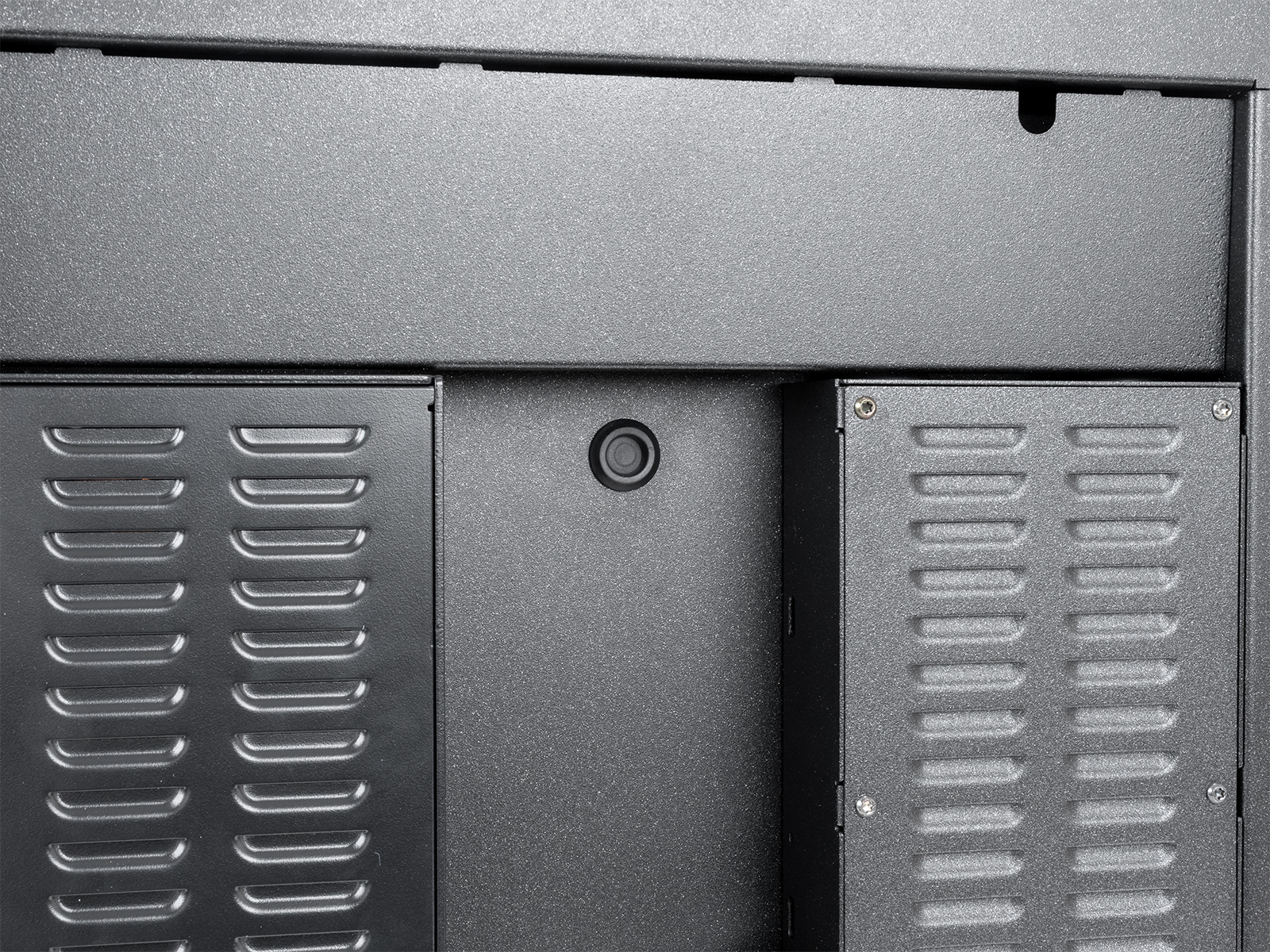 | 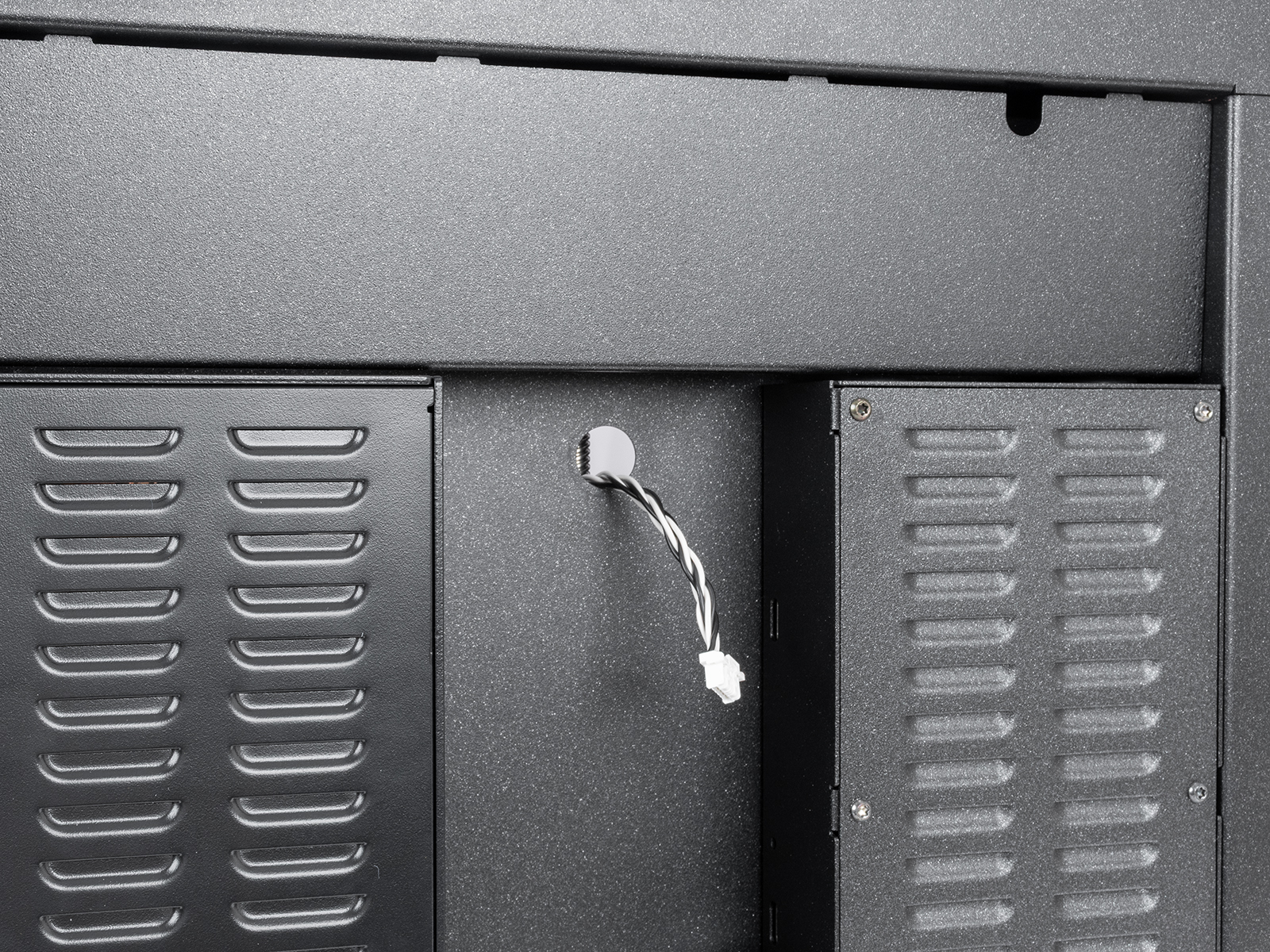 |
Conecta el cable del acelerómetro al conector situado en la parte posterior de la impresora. 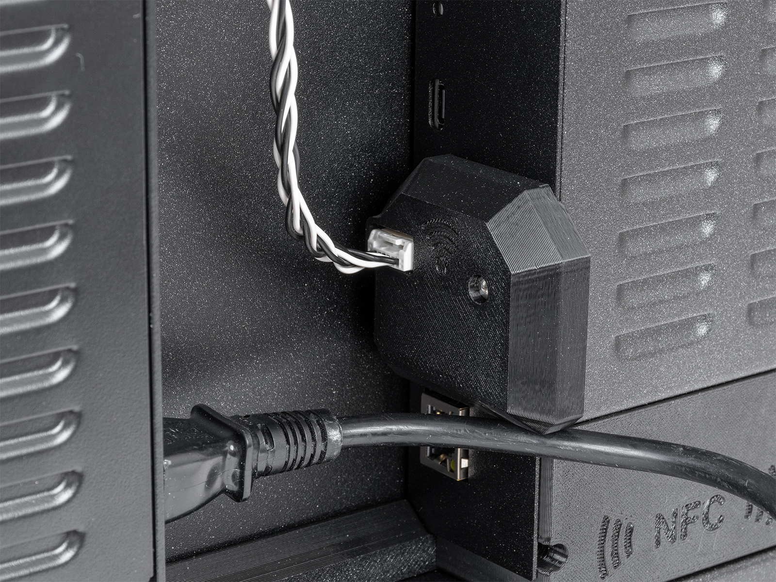

Original Prusa MK4/S, MK3.9/S
En las MK4S y MK3.9S, conecta el acelerómetro al puerto dedicado en la placa xBuddy.
Como alternativa, puedes instalar un cable de puente corto entre el xBuddy y el módulo Wi-Fi de la parte posterior de la impresora. A continuación, puedes conectar el acelerómetro al conector en la parte posterior de la impresora.
En la MK4 y MK3.9, conecta el cable a la placa de circuito impreso del acelerómetro y coloca las cubiertas impresas. El acelerómetro se conecta directamente al puerto dedicado en la placa xBuddy.
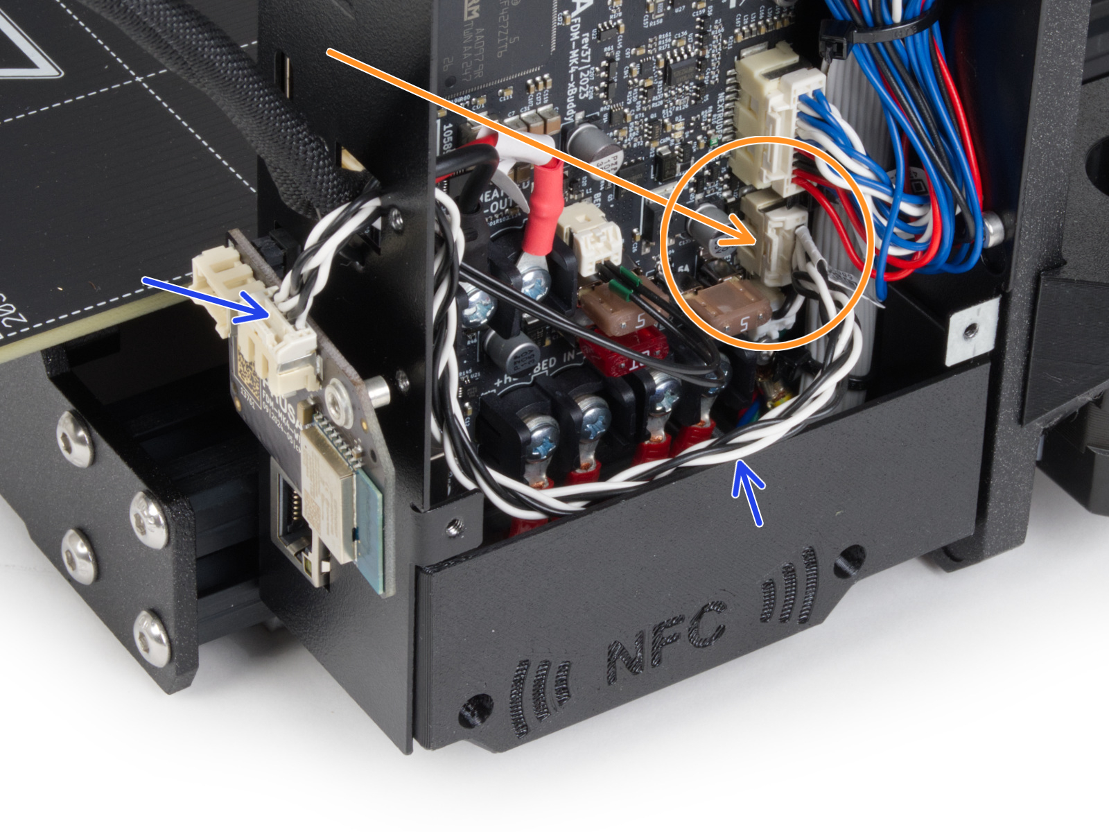 | 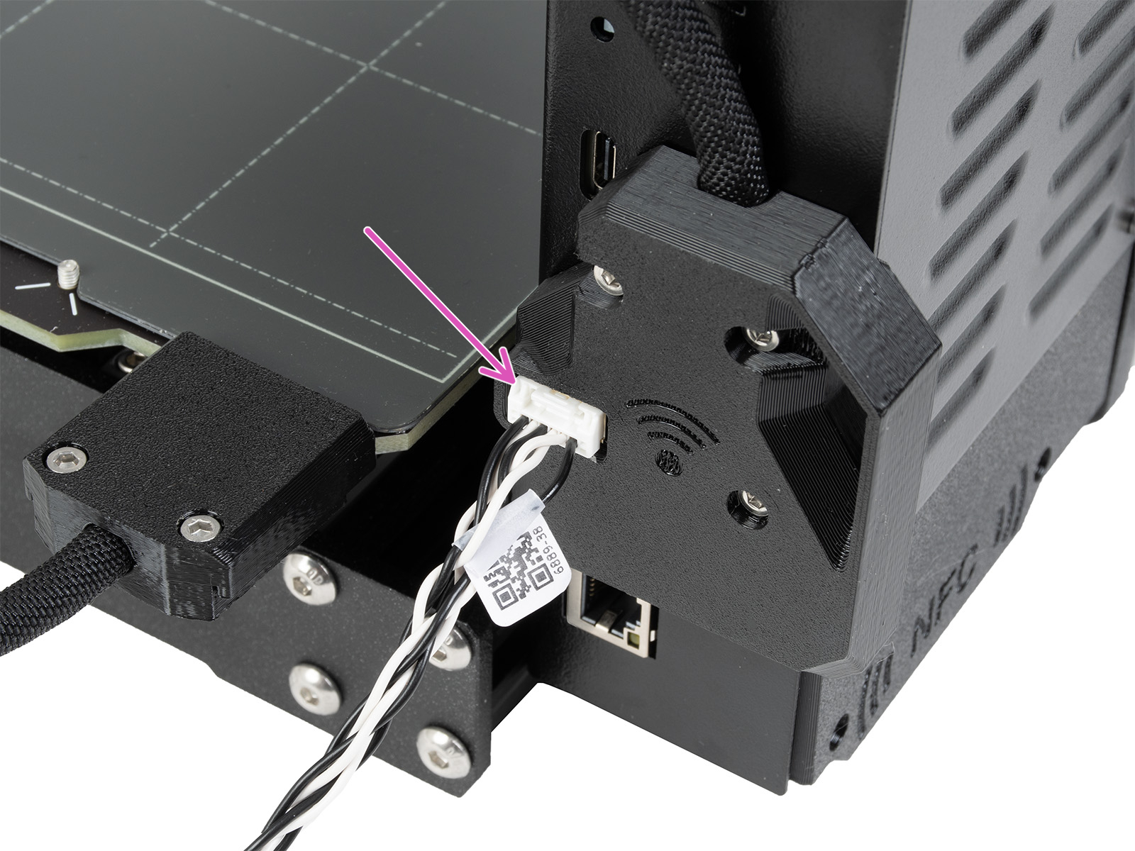 |
Conexión del acelerómetro en la MK4S y MK3.9S
Original Prusa MK3.5/S
Para la MK3.5 o MK3.5S, por favor visita esta guía dedicada.
Calibración
El acelerómetro se utiliza para calibrar los parámetros de input shaper. Puedes iniciar la calibración desde el menú LCD -> Ajustes -> Input Shaper -> Calibración.
Eje X
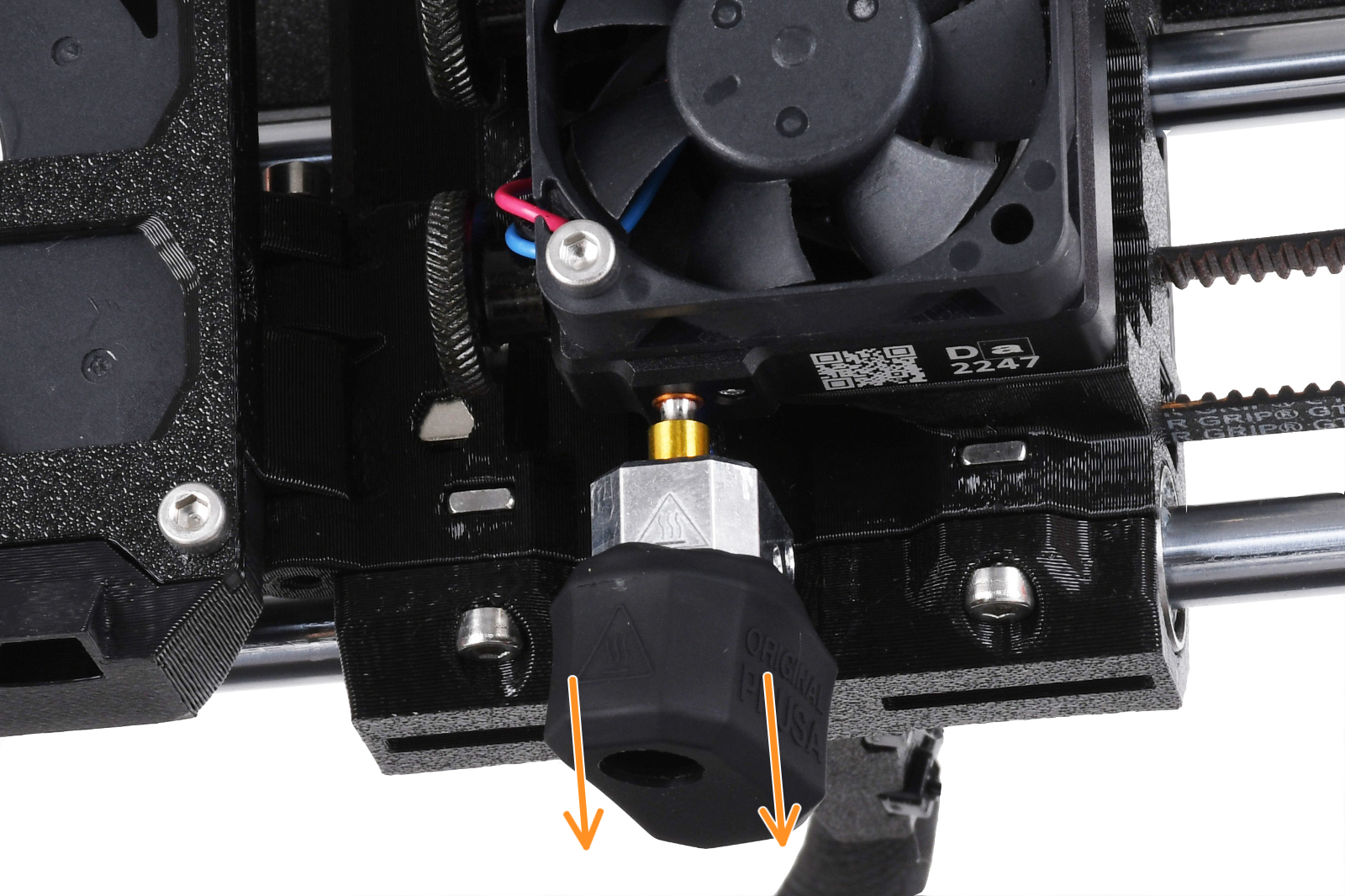
En la MK3.9 o MK4, abre la fan-door completamente antes del procedimiento. Retira el the calcetín de silicona, si está instalado. Identificar la parte del acelerómetro que tiene la forma del bloque calefactor.
 | 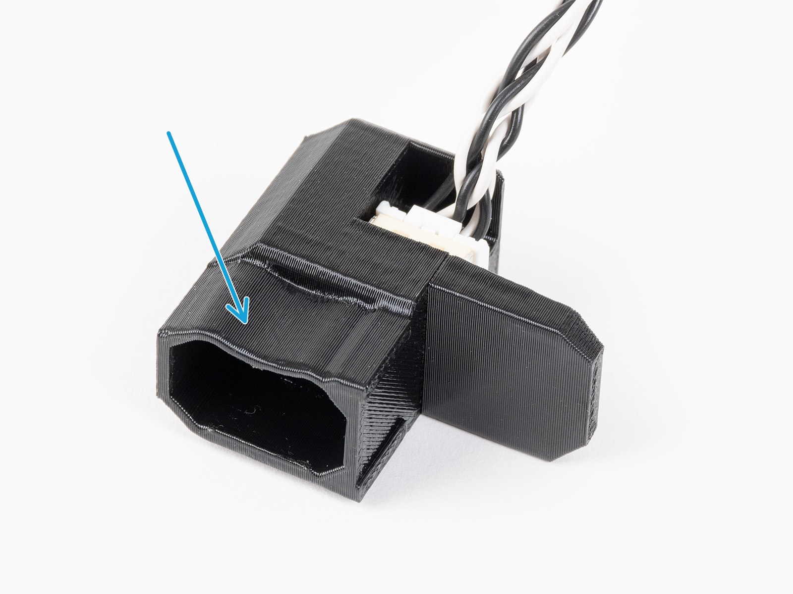 |
Coloca el acelerómetro en el bloque calefactor, empujándolo desde la parte inferior del hotend. Si hay alguna resistencia, no intente empujar el acelerómetro con más fuerza, ya que una fuerza excesiva podría doblar el disipador de calor..
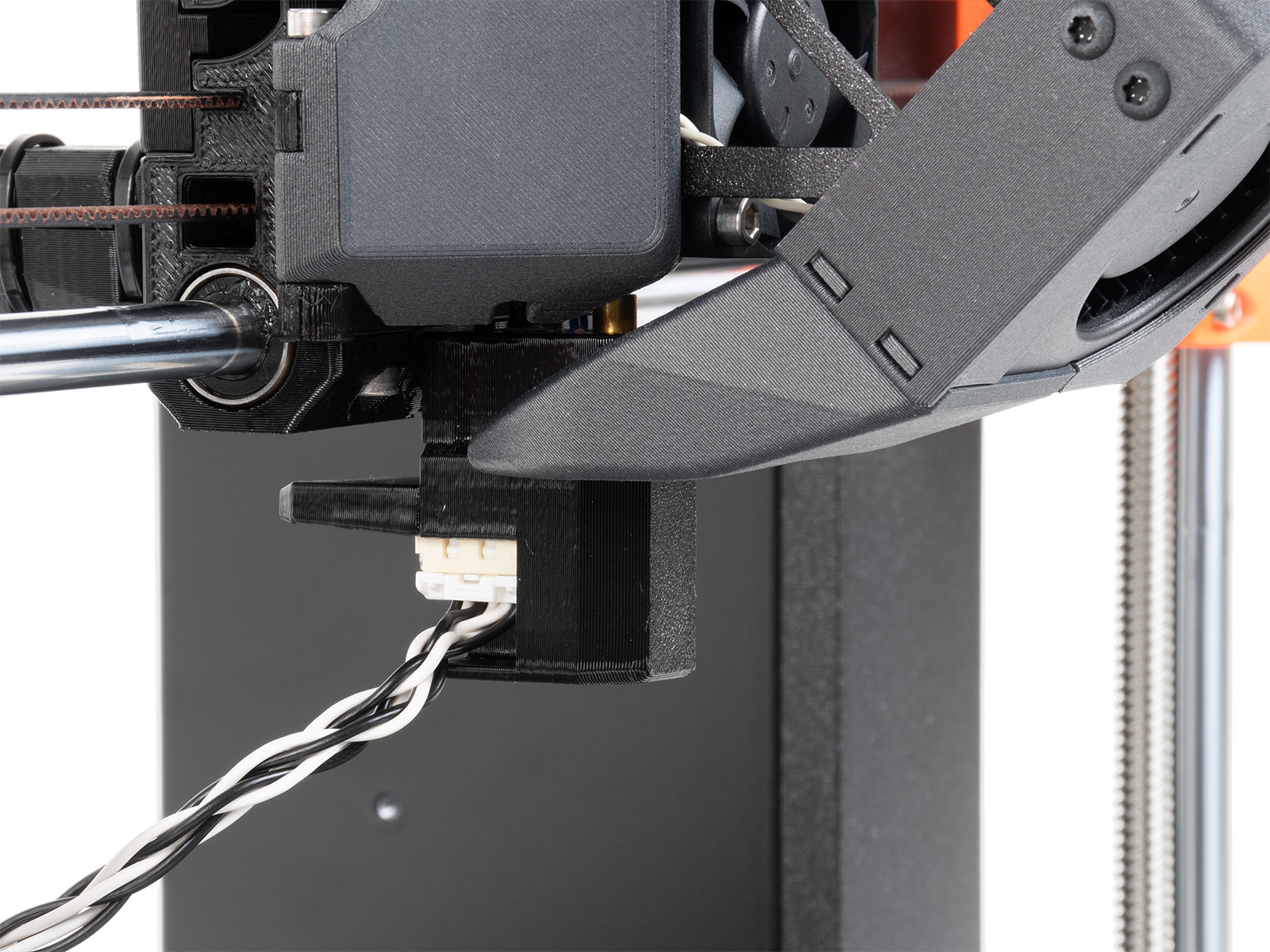 | 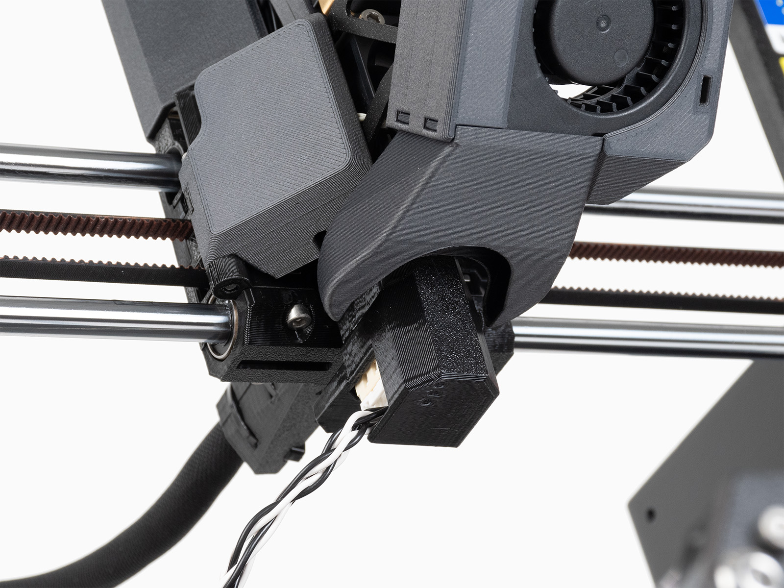 |
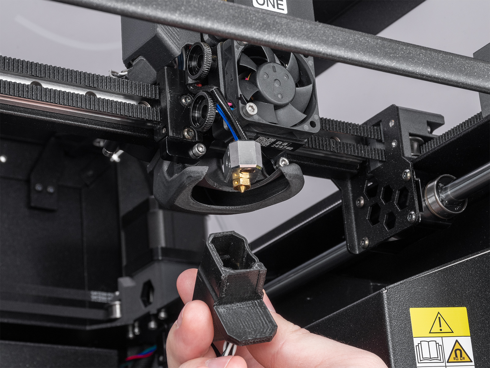 | 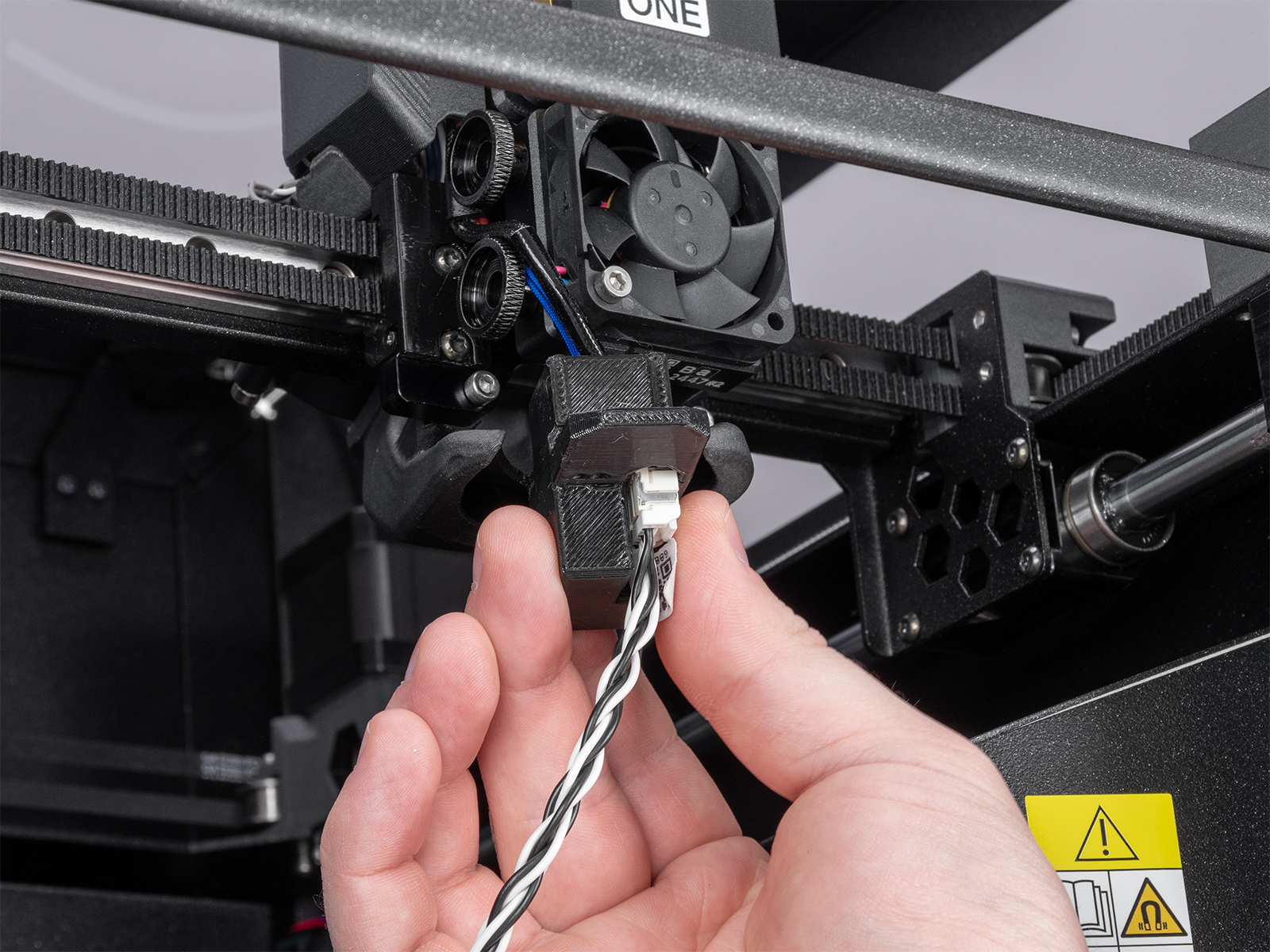 |
Eje Y (MK4/S, MK3.9/S, MK3.5/S)
Identifica la parte del acelerómetro que sobresale del resto. En la parte delantera del eje Y, coloca el saliente entre la lámina flexible y la base calefactable.
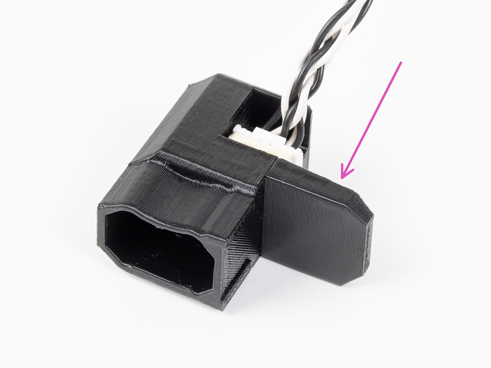 | 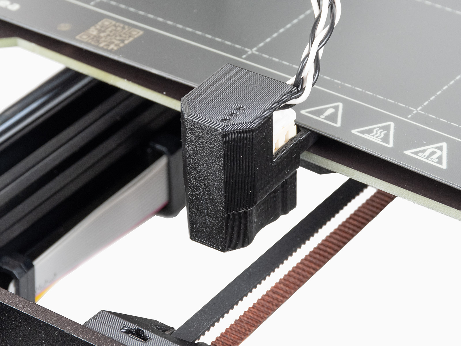 |
Resultados
Los resultados mostrados en la pantalla de la impresora al final de la calibración indican el valor óptimo del tipo de input shaping y frecuencia encontrados con la calibración.