English
Login
3D printers
Materials
Parts & Accessories
For Business
Software
3D Models
Community
Help
Courses
Blog
Company
Support
Original Prusa XL
Printer maintenance
How to replace a Z-axis linear rail (XL) | Begin assembly
1. Begin assembly
Step 1 of 51 (Chapter 20 of 42)
Contents
Comments
Difficulty
Difficult
Available languages
Begin assembly
Contents
Printer maintenance
How to replace the CoreXY plastic parts
How to install the Nextruder V6 Nozzle Adapter (XL single-tool)
How to replace the Prusa Nozzle (XL single-tool)
How to replace the Hotend assembly (XL single-tool)
Packing printer for transport - Original Packing Material (XL)
How to replace the Prusa Nozzle (XL multi-tool)
How to replace a Z-axis motor (XL)
Packing the XL Multi-tool for return - Original Packing material
How to replace a heatbed tile and a heatbed tile cable (XL)
How to replace a print fan (XL single tool)
How to fix Modular bed error (HW solution)
How to replace trapezoid nuts (XL)
How to clean the side filament sensor (XL)
How to change xLCD and xLCD cable (XL single-tool)
How to replace a Dwarf board (XL multi-tool)
How to replace Nextruder heatsink (XL Multi-tool)
How to replace a Dwarf board (XL single-tool)
How to replace the Hotend assembly (XL multi-tool)
How to replace a hotend thermistor (XL Single-Tool)
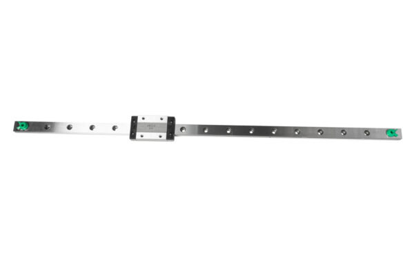
How to replace a Z-axis linear rail (XL)
Begin assembly
Introduction
CAUTION: Lubricant Handling
Alignment Tool
Necessary tools
Unloading filament
Preparing the printer - removing side accessories
Printer preparing
Disassembling side filament sensor
Removing the frame-rear-cover
Placing the printer
Uncovering the Z-axis motor cable - bottom
Uncovering the Z-axis motor cable - rear
Releasing the Z-axis motor - part 1
Releasing the Z-axis motor - part 2
Pulling out the Z-axis motor
Removing the Z-axis arm (left)
Removing the Z-axis arm (right)
Removing the linear rail
Linear rail replacement - parts preparation
Installing the linear rail part 1 (left)
Installing the linear rail part 2 (left)
Installing the Z-axis arm (left)
Installing the linear rail part 1 (right)
Installing the linear rail part 2 (right)
Installing the Z-axis arm (right)
Z-axis motor attaching
Securing the Z-axis motor: parts preparation
Securing the Z-axis motor
Securing the trapezoid nut
Securing the Bed-frame
Covering the Z-axis motor - bottom
Covering the Z-axis motor - rear
Turning the printer
Tightening the frame-rear-cover
Preparing the Filament sensor
Attaching the filament sensor
Installing the Wi-Fi antenna: parts preparation
Installing the Wi-Fi antenna
Spool holder assembly versions
Version A: Assembling the spool holder: parts preparation
Version A: Assembling the spool holder: adjusting the nut
Version A: Assembling the spool holder
Version A: Mounting the spool holder assembly
Version B: Assembling the spool holder: parts preparation
Version B: Assembling the spool holder: adjusting the nut
Version B: Assembling the spool holder
Version B: Preparing the spool holder
Version B: Mounting the spool holder assembly
Z alignment calibration
Good job!
How to replace a profile insert (XL)
How to replace the hotend fan (XL Multi-tool)
How to replace a PSU (XL)
How to replace a hotend heater (XL Single-Tool)
How to lubricate the coupler pins on Original Prusa XL (Multi-Tool)
How to replace the tch-profile-insert (XL)
How to replace the Sandwich Board (XL)
How to replace the rubber band on Original Prusa XL (Multi-tool)
How replace the CoreXY Cover Rear (Original Prusa XL)
How to install the Nextruder V6 Nozzle Adapter (XL Multi-Tool)
How to replace a XY motor (XL)
Packing the XL Enclosure for return - Original Packing material
How to change the belt (XL)
How to replace the main cable connector cover (XL)
How to replace the PDU splitter (XL)
How to replace the print fan (XL multi-tool)
How to replace trapezoid nuts (XL)
How to lubricate linear bearing rails (XL)
How to change the xLCD (XL)
How to set up a Buddy3D Cam
How to replace Nextruder heatsink (XL Single-tool)
How to replace a Nextruder (XL single-tool)
Comments
Log in
to post a comment
No comments