English
Login
3D printers
Materials
Parts & Accessories
For Business
Software
3D Models
Community
Help
Courses
Blog
Company
Support
Original Prusa i3 MK3S
Printer maintenance
How to replace an IR-sensor (MK3S/MK3S+) | Begin assembly
1. Begin assembly
Step 1 of 29 (Chapter 4 of 17)
Contents
Comments
Difficulty
Moderate
Available languages
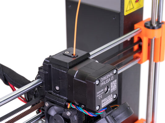
Begin assembly
Contents
Printer maintenance
How to replace a hotend thermistor (MK3S/MK3S+)
How to replace a print fan (MK3S/MK3S+)
How to replace a hotend (MK3S/MK3S+)
How to replace an IR-sensor (MK3S/MK3S+)
Begin assembly
Introduction
Tools necessary for the IR-sensor replacement
Preparing the printer
Removing the IR-sensor
New IR-sensor - parts preparation
Installing the new IR-sensor
Checking the connector
Tools necessary for the IR-sensor cable replacement
Preparing the printer
Disconnecting the IR-sensor cable
Removing the textile sleeve
Removing the x-carriage-back
Extruder surgery
Extruder surgery
Removing the IR-sensor cable
New IR-sensor - parts preparation
Guiding the new IR-sensor cable
Reassembly of the extruder
Reassembly of the extruder
Mounting the hotend fan
Mounting the x-carriage-back
Mounting the x-carriage-back
Tightening the textile sleeve
Tightening the textile sleeve
Connecting the IR-sensor cable
Guiding the textile sleeve
Final check
It's done!
How to replace a P.I.N.D.A. sensor (MK3S)
How to replace SuperPINDA (MK3S/MK3S+)
How to replace a hotend heater (MK3S/MK3S+)
How to replace a heatbreak/heatsink/heaterblock (MK3S+/MK3S/MK2.5S/MMU2S)
How to trim PTFE tube - Multi Material
How to post-process the printed parts
How to replace a heatbed thermistor (MK3S+/MK3S/MK2.5S/MK2S)
How to replace PSU on MK3 printers
How to replace a hotend PTFE tube (MK3S+/MK3S/MK2.5S/MMU2S)
How to replace a hotend thermistor (MK2S)
How to trim PTFE tube - Original Prusa printers
Maintenance tips
Replacing the PEI sheet on the (MK3S/MK3/MK2.5S/MK2.5)
Comments
Log in
to post a comment
No comments