日本語
Login
3Dプリンター
マテリアル
部品 & アクセサリー
法人向け
ソフトウェア
3Dモデル
コミュニティ
ヘルプ
コース一覧
ブログ
会社概要
サポート
Original Prusa i3 MK3
Original Prusa i3 MK3キット組立て
8. Electronics assembly (B3/R2 design) | Tools necessary for this chapter
1. Tools necessary for this chapter
ステップ 1 / 39 (章 11 / 14)
内容
コメント
⬢
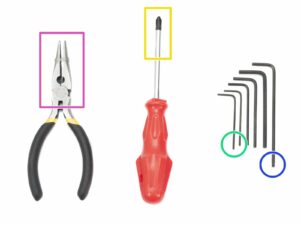
結束バンドの切断に使用するラジオペンチ
⬢
M3 ネジ 向けの 2.5mm 六角レンチ
⬢
ナットの調整用の 1.5mm 六角レンチ
⬢
PSUケーブルやヒートベッドケーブル締め付け用プラスドライバー
Loading...
次
内容
Original Prusa i3 MK3キット組立て
1. はじめに
Introduction
2. Y軸の組み立て
3. X軸の組み立て
4. Z軸 の組み立て
5. E軸の組み立て (スパイラルチューブ)
5. E軸の組み立て (ケーブルスリーブ)
6. LCD の組み立て
7. ヒートベッドと電源ユニットの組み立て (スパイラルチューブ)
7. ヒートベッドと電源ユニットの組み立て (ケーブルスリーブ)
8. 電子部品の組み立て (B3/R2 デザイン)
Tools necessary for this chapter
Preparing the RAMBo-cover-door (part 1)
Preparing the RAMBo-cover-door (part 2)
Identifying mount holes
下側のヒンジの準備
RAMBo-cover-door assembly
Wrapping X-axis cable
EINSY RAMBo board - different versions
Preparing the RAMBo-cover-base (part 1)
Preparing the RAMBo-cover-base (part 2)
Mounting the RAMBo-cover-base (part 1)
Mounting the RAMBo-cover-base (part 2)
Mounting the RAMBo-cover-base (part 3)
ケーブルの整理 (パート 1)
ケーブルの整理 (パート 2)
ケーブルの整理 (パート 3)
ケーブルの整理 (パート 4)
ケーブルの整理 (パート 5)
ケーブルの整理 (パート 6)
ケーブルの整理 (パート 7)
ケーブルの整理 (パート 8)
ヒートベッドケーブルの束を接続する
PSU and HB power cables (part 1)
PSU and HB power cables (part 2)
すべてのモーターの接続(X/Y/Z軸)
パワーパニック と ヒートベッドサーミスター のケーブル
Connecting the extruder cable bundle (part 1)
エクストルーダーのケーブル束を接続する(パート2)
エクストルーダーのケーブル束を接続する(パート3)
エクストルーダーのケーブル束を接続する(パート4)
LCD ケーブル を接続する
すべての接続をもう一度確認しましょう!
Finalizing the RAMBo cover
Mounting antivibration feet
Different spool holder design
Mounting the single spool holder
Assembling the double spool holder
ダブルスプールホルダーを取り付ける
Hooray!
8. 電子部品の組み立て (B7/R2 デザイン)
9. プリフライト確認
マニュアルの変更ログ
コメント
ログイン
してコメントを投稿する
コメントなし