In some cases, you might want to cut a model into multiple pieces before printing:
- The model is too big to be printed in one piece.
- You only want to print a part of a model.
- A part of the model needs a different print orientation for added strength.
- Printing the model in one piece would require a needlessly large amount of support material.
PrusaSlicer provides an advanced cutting function:
- Cut models at any angle.
- Select which parts to separate and which to keep connected.
- Generate connectors and dowel pins for easy assembly.
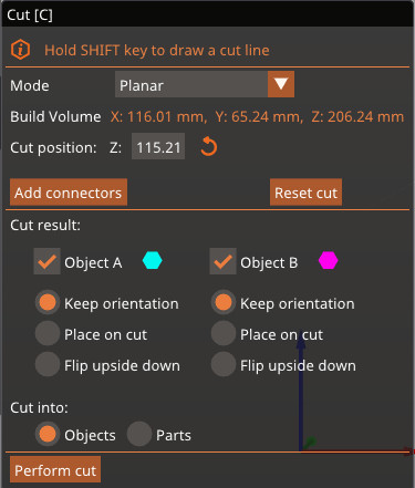
Select the object and press the C key or pick the Cut tool from the left toolbar. A widget showing the cutting plane will appear on the object, and a context menu will appear on the left side menu. On the menu, you can choose Planar mode or Dovetail mode.
Planar mode
If planar mode is selected, the cut will be made on a straight plane wherever you place the cutting widget. With this widget, you can select where the cut will be placed in the Z, X, and Y axes.
Enter an exact value [mm] in the context menu to set the cutting plane position on the Z axis. To change the rotation of the cutting plane, use the arrows on top of the cutting widget.
The cut widget can be placed back in the initial position by clicking the Reset cut button. Note that this will also remove the connectors.
 |  |
Connectors
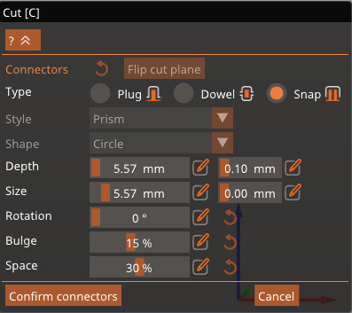
Under the axes information, you can add connectors between the cut parts. When this option is selected, a new menu will show to format the connector. Use the left mouse button to add a connector, and the right button to remove it.
The standard connector is a circular prism plug, but you can choose between three different types of connectors:
- Plug: adds a plug to the side of the cut and subtracts the space for it from the other side
- Dowel: subtracts the pin from both sides and generates an extra object to print as the connector
- Snap: Adds a snap-fit connector on one side and subtracts the space to fit it on the other side
You can also choose the plugs' style, shape, depth size, and rotation. If you wish to change the side of the cut for the plug and snap connectors, click on Flip cut plane.
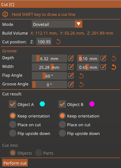
Dovetail mode
The Dovetail mode creates a pin and a tail in a trapezoidal shape on the cut plane. When this option is selected, the cut widget has the same movement as the planar mode, as well as an arrow to adjust the position of the tail. Under the axes information, it is possible to adjust the dimensions of the tail.
Cut result
It is possible to choose if the cut will form two different objects, or if it will cut the same object into two different parts.
If the option to cut the object into parts is selected, the object will be split into two different sectors that can have different settings, but they will remain connected. Note that this option is not available if the Dovetail mode is selected.
If the option cut into parts is selected, it is possible to choose what happens to each new object: keep the current orientation, place the part where the cut was made down on the print surface, or flip the part upside down from the current orientation.
Other features
Select which parts to separate and which to keep connected
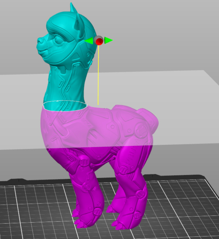
If the cutting plane intersects the model in several different regions, you can select which parts to cut and which to keep connected by right-clicking them.
Add cut plane
You can also hold down the Shift key and click on two points on the screen to quickly define a cutting plane. The cutting plane will be perpendicular to the current view.
24 comments
The manual page here doesn't discuss this at all, but it seems like the main and best motivation for having the Cut feature on the Slicer. Can you shed any light on this?
I have a screenshot of what I mean but not sure how to post it here
Otherwise it's a cool feature.
Is there a way to loosen the dovetail fit of the parts so they don't fit together so tightly? I am having issues with fitment