Every firmware version goes through intense testing to verify that every single feature works as it should. That applies especially to the safety features: for example, if the thermistor readings are outside the limits, the heating stops automatically.
Official firmware is signed with a private key and the printer verifies the validity of this signature before it allows a firmware update.
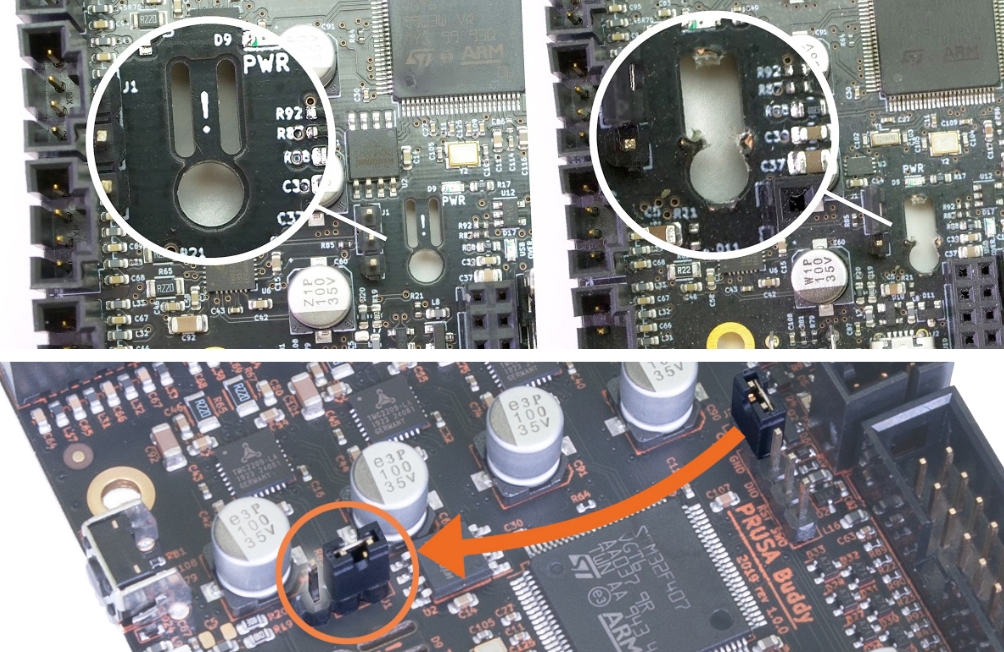
To flash your own (or a community-made) unsigned firmware, you’ll have to break the appendix seal on the Buddy board and move the jumper in the correct position.
- Turn off and unplug the printer.
- Pull out the power switch to access the appendix (1).
- Take a small thin screwdriver, insert it into the long hole furthest from the wall of the case, and carefully remove the middle part.

- Check the three pins above it - there must be a black jumper on the two pins that are closer to the center of the board.
Some revisions of the board will only have two pins for the jumper. You will then not need the jumper at all! Only break the appendix seal to flash unsigned firmware. A jumper on these pins can even prohibit the firmware from being updated.

Breaking the appendix seal won’t void your warranty, so you are free to flash custom firmware.
However, since there is no way for us to verify or test every single custom firmware on the internet, we disclaim liability for any kind of damage or harm a printer with a broken seal may cause (e.g. in case of a fire).
So, please, don’t mindlessly flash suspicious files!
However, since there is no way for us to verify or test every single custom firmware on the internet, we disclaim liability for any kind of damage or harm a printer with a broken seal may cause (e.g. in case of a fire).
So, please, don’t mindlessly flash suspicious files!
Was this article helpful?
This action is available only to registered users. Please log-in.
8 comments
For example, my educated guess is that breaking the indicated PCB section disables firmware verification - so I can compile and load a firmware myself using the usual method (by placing a .bbf file on a USB Mass Storage device and rebooting), while moving the jumpers places the board into a reflashing mode so I can connect it directly to a laptop to ... use what software to talk to it? And what would the laptop and board talk about?
Personally, I just want to change a #define of the official firmware, compile it, and flash it on. If the printer no longer boots after making this change then I wouldn't want to undertake it.
Clarifications would be greatly appreciated.