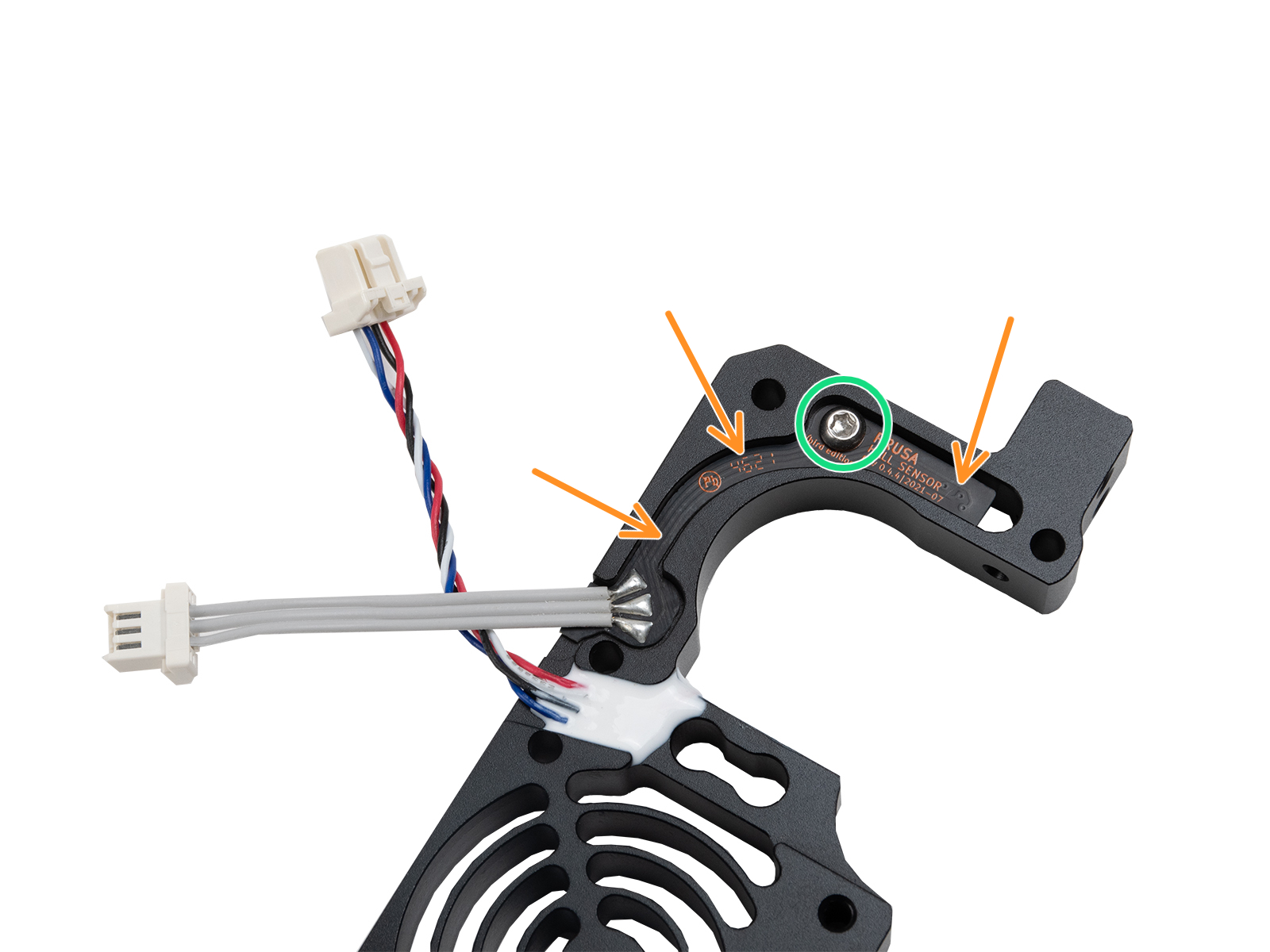
The filament sensor equipped on our Nextruder printers detects the presence of a filament and filament run-out. The sensor is a Hall sensor, triggered by a mechanism composed of a spring, a magnet, and a ball.
On printers upgraded to the Original Prusa MMU3, some of the Nextruder components are modified, including the mechanism that triggers the filament sensor. In these printer versions, the mechanism does not rely on a system of spring, magnet, and ball, but is based on the idler tension bolt.
Check assembly (MK4/S, MK3.9/S)
If your printer is an MK4 or MK3.9, you have received a package with magnets for the assembly. On MK4S and MK3.9S, as well as CORE One and XL, this subcomponent comes pre-assembled in the heatsink.
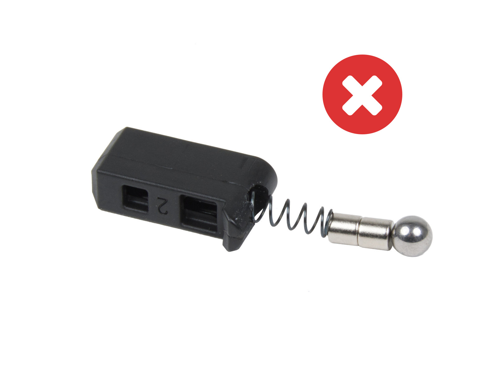
Note that two magnets are sent, but one is meant to be used in the assembly, and the other is a spare. If your filament sensor does not work, check if two magnets have not been added by accident.
 |  |
Nextruder with MMU3 modification
When the MMU3 is installed on the MK3.9/S or MK4/S, the Prusa-ball-holder is replaced by a swivel assembly. If you have the MMU modification in your extruder, the steps below still apply, but are applied to the swivel assembly whenever the Prusa-ball-holder is mentioned.
How to clean the filament sensor
During usage, filament residue might build up around the sensor or its mechanism, possibly causing false readings and thus malfunctioning.
1) Compressed air
At the top of the extruder is a small hole, insert the tip of a compressed air can in the hole. With your free hand, prepare a bit of filament with a non-stringy tip. Repeatedly insert and remove the filament from the extruder, while blowing the compressed air. This will dislodge the build-up debris.
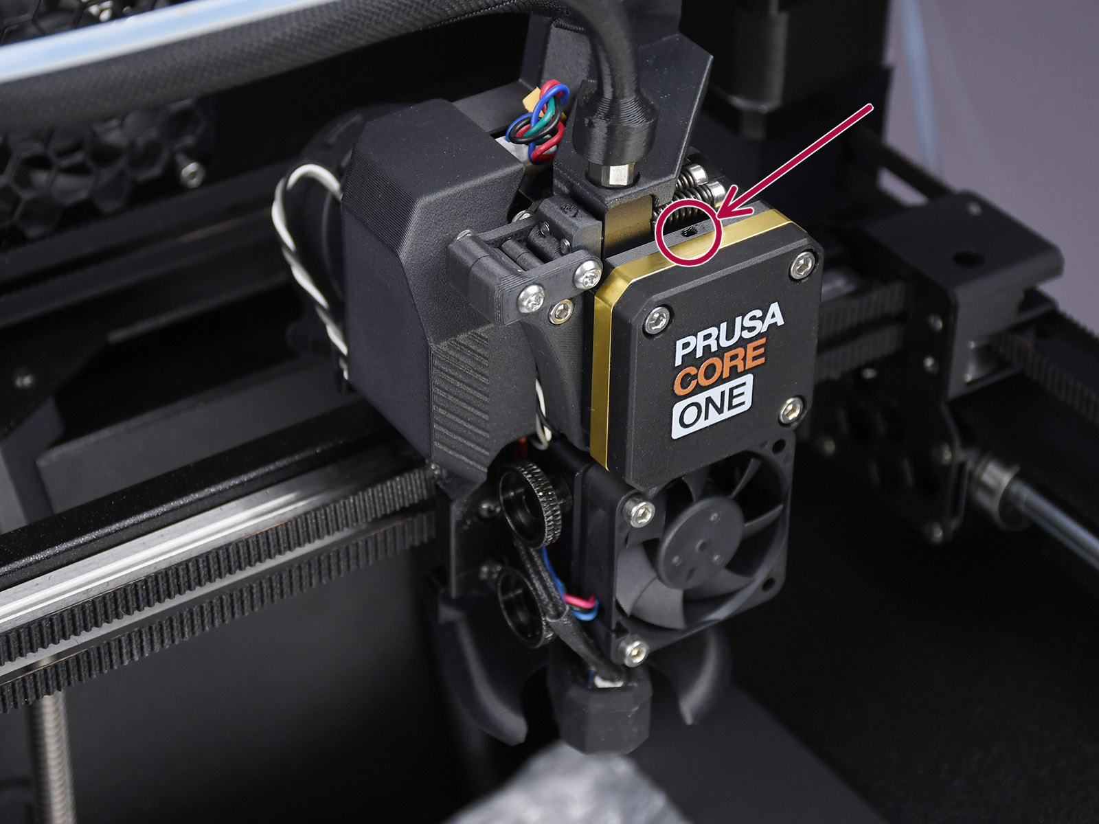 | 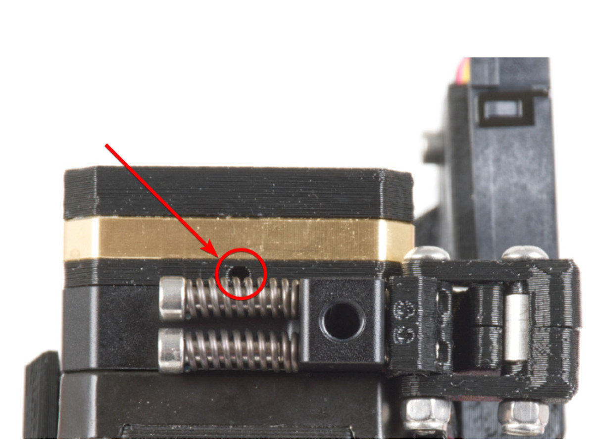 |
Top view of the CORE One (left) and MK4 (right) print head. The XL print head has a similarly positioned small hole.
2) Filament tip insertion
In case you don't have compressed air at hand, a similar procedure to the one above can be attempted.
Prepare a bit of filament with a non-stringy tip. Repeatedly insert and remove the filament from the extruder. It will be necessary to insert and remove the bit of filament several times to achieve good cleaning, and the technique might not always be effective.
3) Removing the sensor
If the previous techniques do not work, the filament sensor can be removed to be manually cleaned. This procedure requires partial disassembly of the Nextruder.
On XL, make sure the firmware version is 6.4.0 or higher, to have access to the needed gearbox alignment procedure from the printer menu. The CORE One, MK4/S, and MK3.9/S have this procedure accessible on all firmware versions.
Ensure to have the PG-assembly-adapter before continuing with the following procedure. If you do not have it, you can purchase it from our e-shop, or you can print it using the files below, depending on the printer you will use.
PG-assembly-adapter e-shop page
PG-assembly-adapter printed with CORE One, MK4/S, MK3.9/S, XL
PG-assembly-adapter printed with MK3/S/+, MK3.5/S
- Unload the filament, then wait for the printer to fully cool down. After that, turn the printer off.
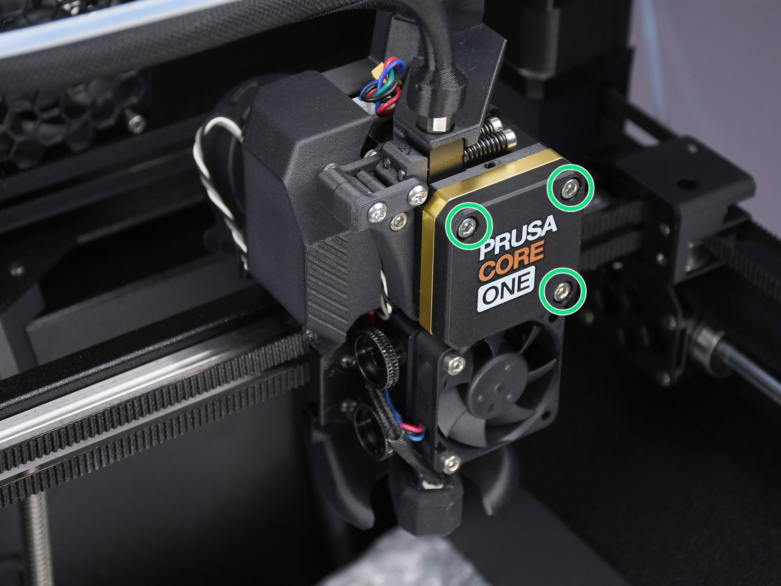
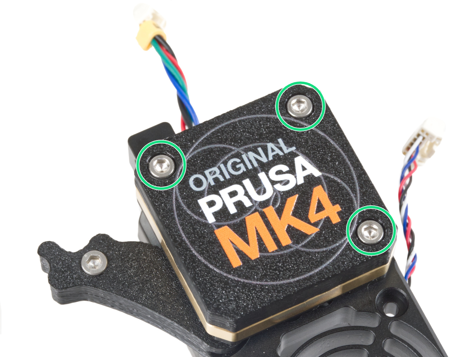
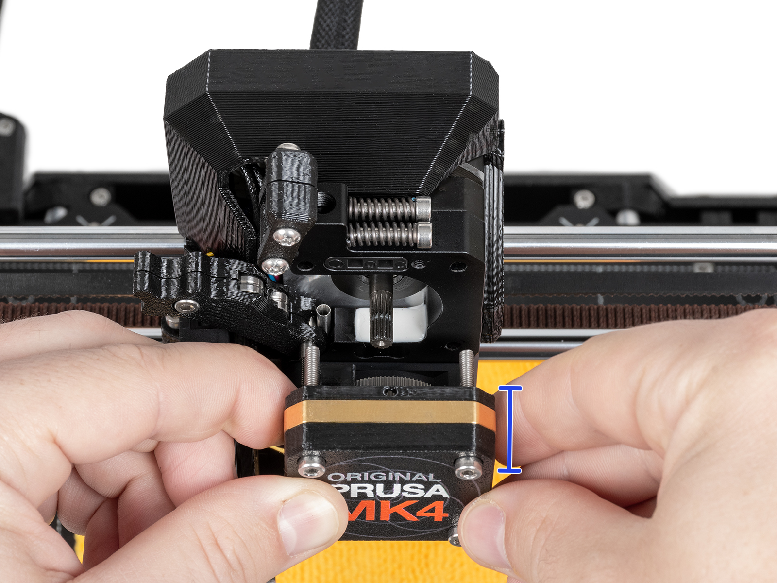
- Remove the PG-case, together with the PG-ring, gearbox, and main plate. Remove all of these parts in one piece.
 |  |
 |  |
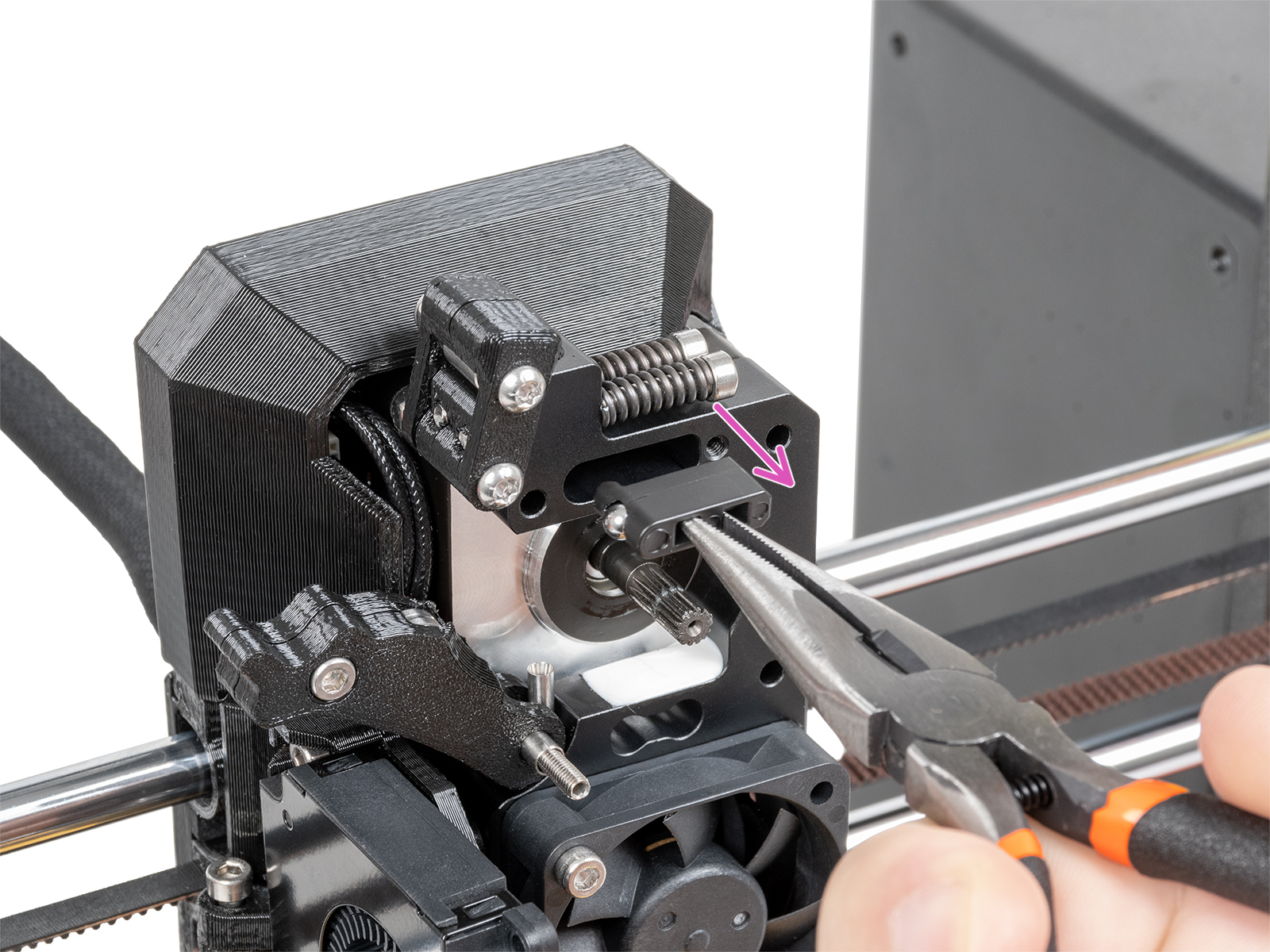
- Remove the Prusa-ball-holder using pliers.
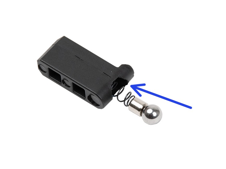
- Carefully remove the ball-magnet-spring combo from the Prusa-ball-holder and clean any debris out of it. Clean also the slot on the heatsink.
 | 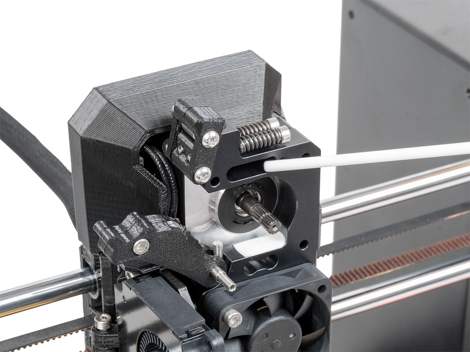 |
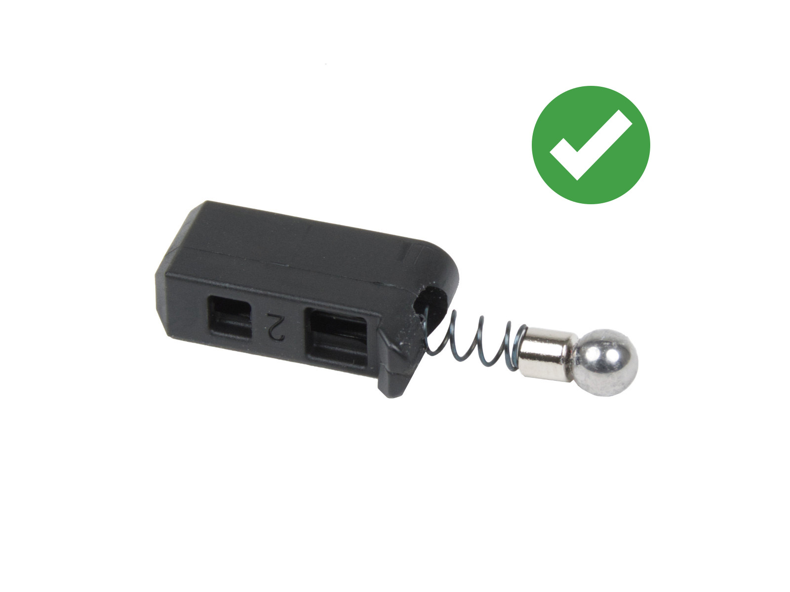
- Reassemble the Prusa-ball-holder in the following order: steel ball, magnet, and spring. Then, insert the assembled Prusa-ball-holder in the Nextruder.
 |  |
- Reassemble the block with PG-case, PG-ring, gearbox, and main plate.
- Perform the gearbox alignment, following the procedure from the dedicated gearbox alignment article.
27 comments
I am having trouble with my upgrade from an MK4s to a Core One. This is my first time reaching out for help since my purchase of the MK3 (made every upgrade since). Usually I can figure anything out or am able to find answer without reaching out here to bother you guys. Anyway, upgrade was pretty straightforward and all went well except, the Nextruder filament sensor. After some research I realized my issue is that the mod used for the sensor to work with MMU3 and Mk4s changer the sensor. Now I realize I can Print missing part and use the leftover magnet, spring and steel ball (if I can find them). But, I am building the CoreBoxx so it would be a waste to have to change sensor just to change back in a month or so. My question is, Is there a way to get the core one to work with the MMU sensor without connecting the MMU? I need the printer so I can print parts for the CoreBoxx . Any help and or Ideas would be great. I realize I'm probably missing something simple that I just don't see...
if you only want to remove the PGcover, (Planetary Gear) and back plate assembly. The 4th (headless) screw, bottom left, only holds the swing arm.