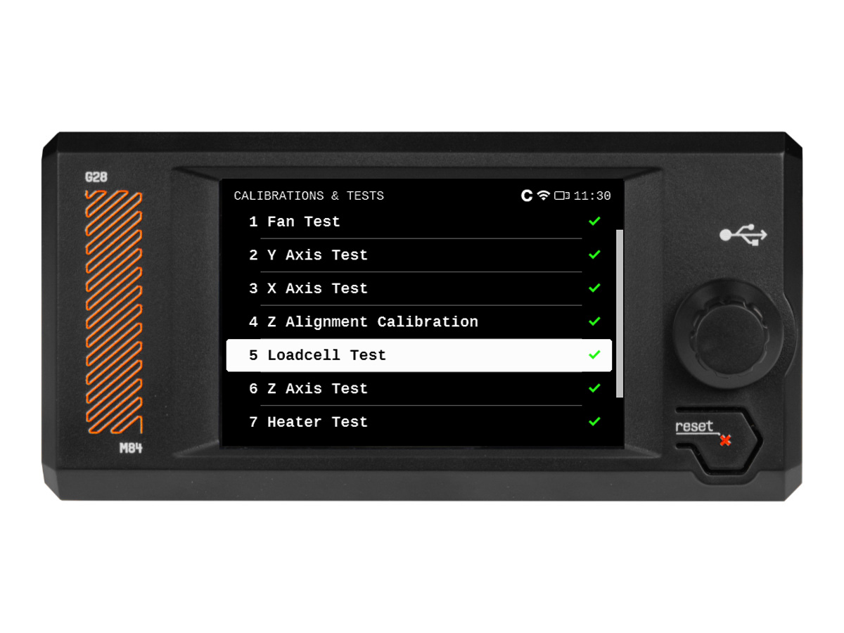
On the Prusa CORE One/+, the selftest checks for issues in the printer's assembly, wiring, and electronic components. It is the first part of the Calibration Wizard, which is prompted automatically when you turn on the printer for the first time or after a factory reset. After the initial calibration is completed, each step of the selftest can be initiated under LCD Menu -> Control -> Calibrations & tests.
Note that if the printer is placed on an unstable surface or if there is another running 3D printer next to it, it may negatively affect the calibration. The printer should be placed on a stable surface.
Selftest procedure checks
- Fan Test
- Door Sensor
- Y Axis Test
- X Axis Test
- Z Alignment Calibration
- Loadcell test
- Z Axis Test
- Heater Test
- Gears Calibration (non-mandatory, meant for kits)
- Filament Sensor Calibration
Selftest results
During the selftest, its results are shown on the screen, indicating success or failure for each point.
Fan testing
The Prusa CORE One/+ selftest procedure will test the hotend fan, the print fan, and the chamber fans. If this issue shows, check:
- Check for any obstruction that could prevent the fan from spinning.
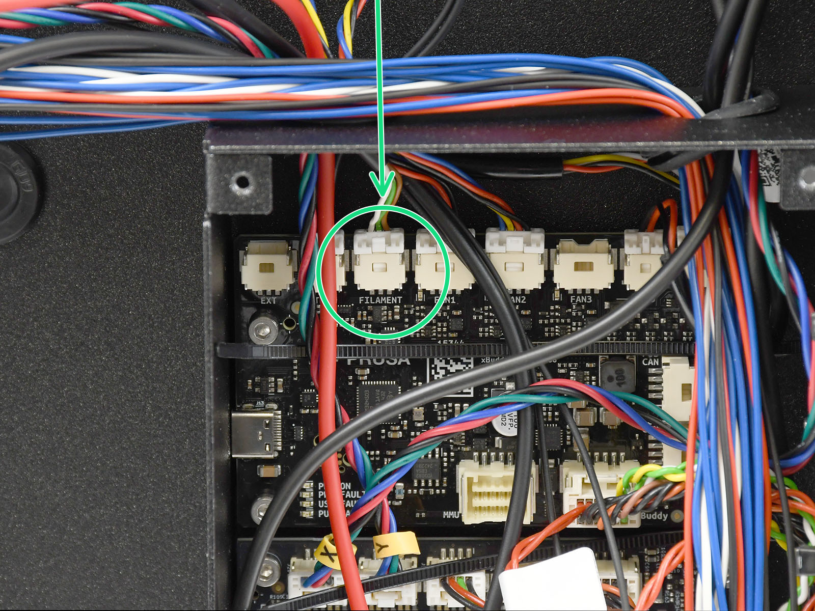
- Ensure that the fans are correctly connected to the LoveBoard or the xBuddy extension board.
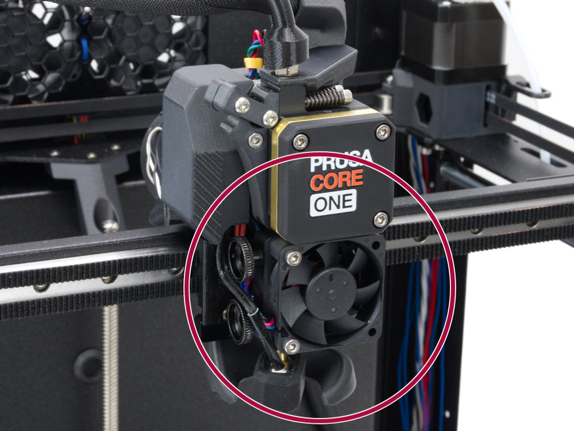
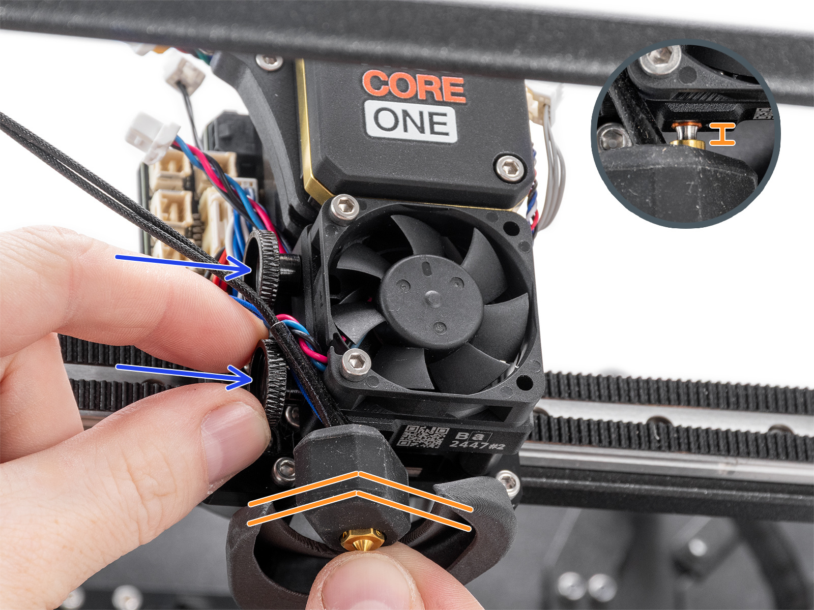
- If the error is on the hotend fan, make sure that it is installed in the correct position and orientation as shown in the image below.
- For the print fan and chamber fans, go to the printer menu to Control -> Temperature, and set the fan to be tested to 100%. See if the fan spins or if it shows any errors.
The printer might show the message "Fan not spinning" instead of a failed selftest. This can also be considered a failed selftest.
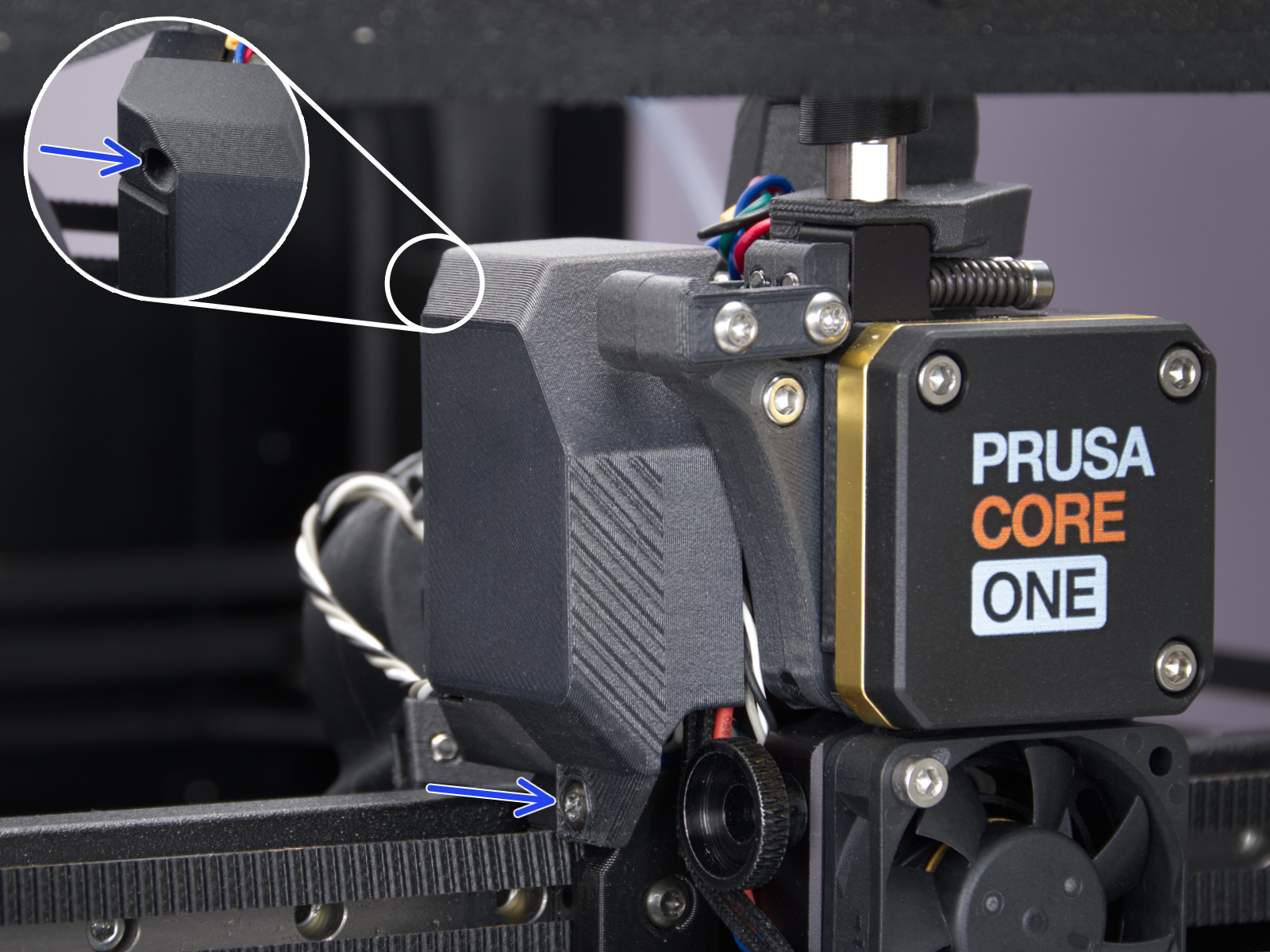 |  |
| Print fan | Hotend fan |
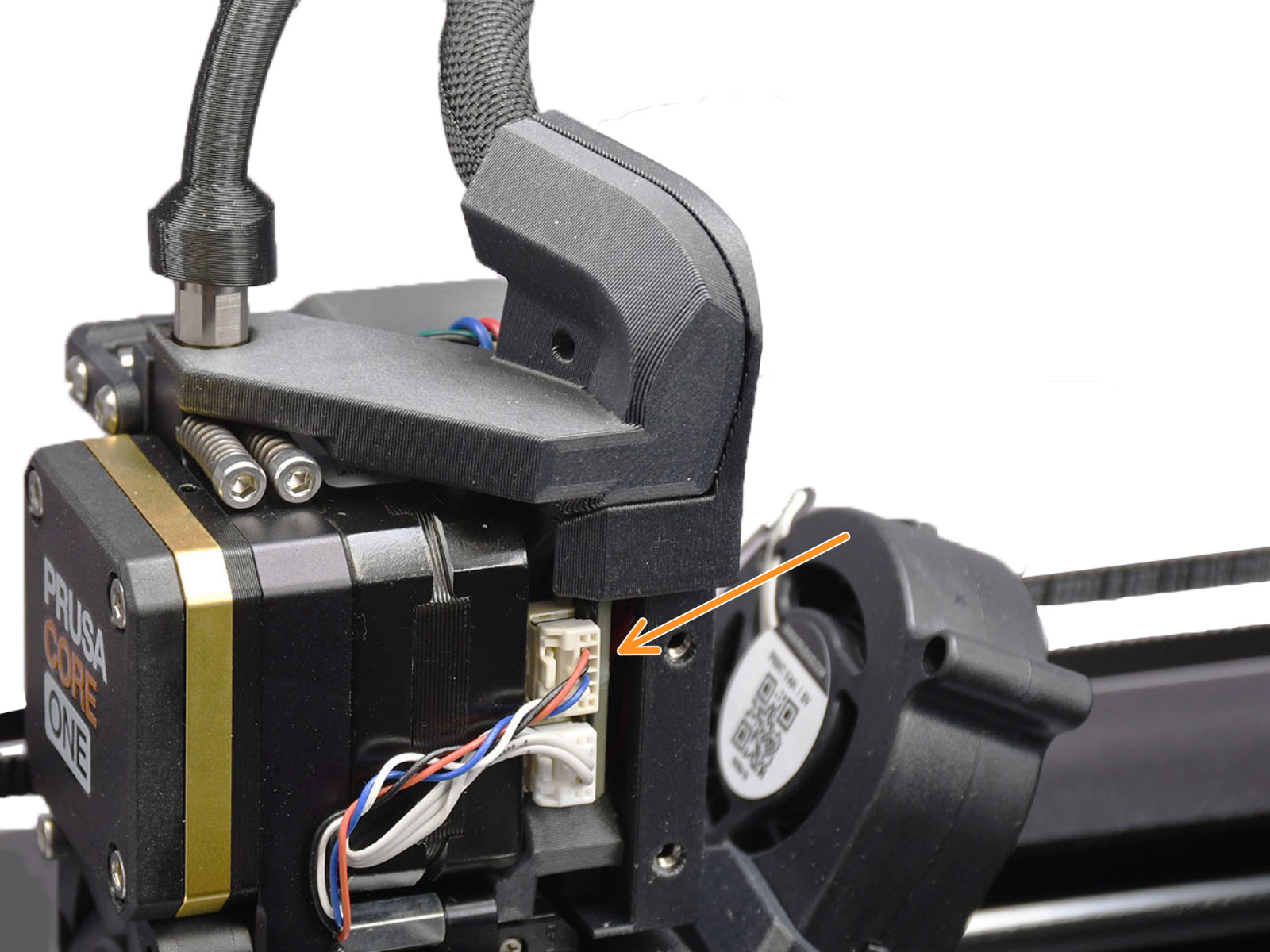
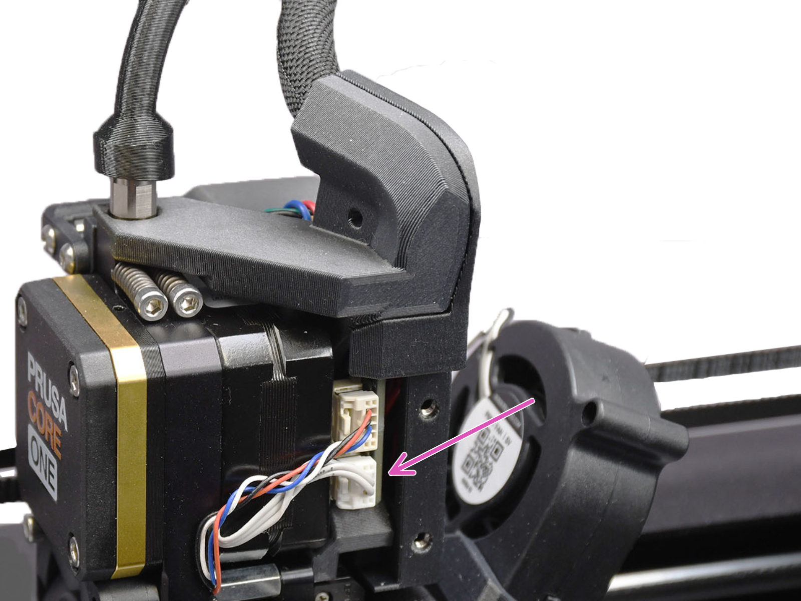
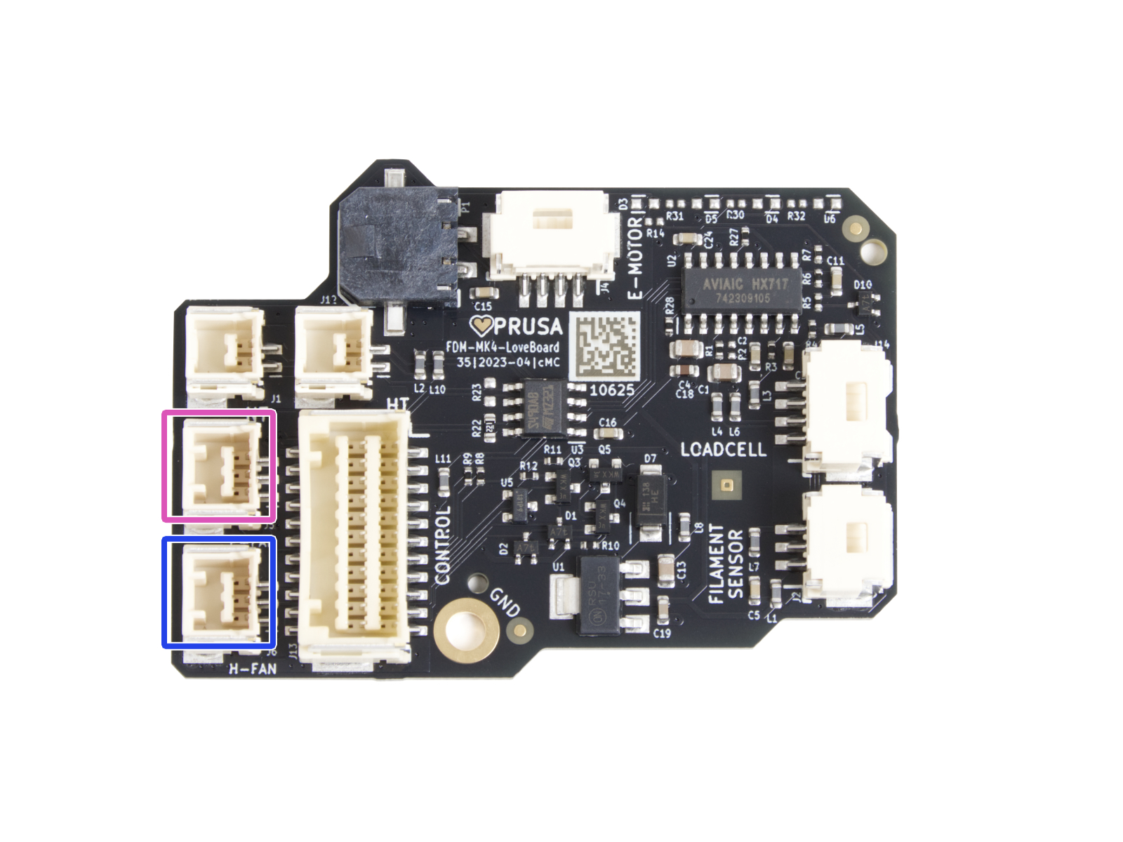 | 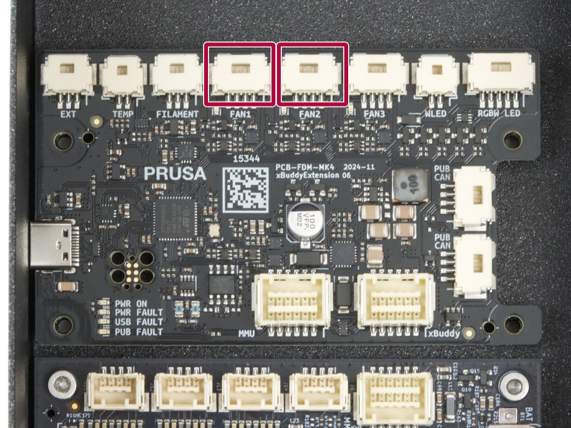 |
| Print fan and hotend fan connectors | Chamber fan connectors |
Door sensor calibration
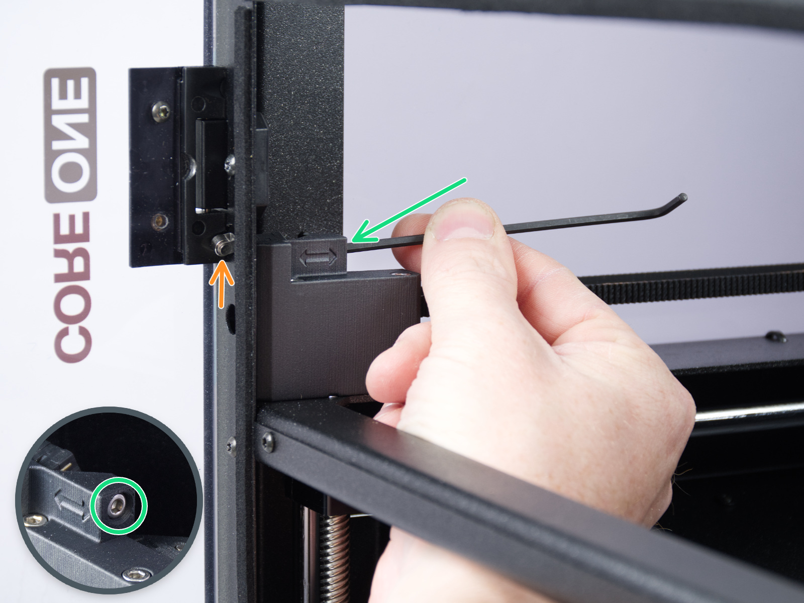
In case the sensor behaves differently from what is expected in the door sensor calibration, it is necessary to check if the sensor is working. Go to the printer menu to Info -> Sensor Info -> Door sensor. Then, try opening and closing the door and see if the sensor is triggered. If the door does not trigger the sensor, try it by pressing the latch with your finger.
If the sensor shows the correct status, go back to the calibration by going to Control -> Calibrations & tests -> Door sensor, and follow the instructions to tighten or loosen the screws.
On the last part of the calibration, the printer prompts you to place your fingers between the door and the frame. This is meant to prevent injury. If there is an issue with this test, you can keep the door completely open to pass the test.
If the door sensor does not work, check the cable length and connection.
Y and X axes test
The printer can determine if the components are moving correctly along each axis.
In case of an issue on the X-axis or the Y-axis, make sure that there is no obstacle to the movement, and readjust the belt tension.
Also, test the printer movement with the stepper motors temporarily disabled (LCD Menu -> Control -> Disable Motors), moving along both XY diagonals.
Move the X-Axis to the front of the CoreXY, and check if both sides are touching the front at the same time. If the sides are not aligned but the belts have the correct tension, do the following procedure:
- Loosen the belts completely. Be careful so that the square nuts do not fall off the plastic parts when removed.
- Check which side sits against the front end (tight side) and which one has to be pushed towards it to touch it (loose side).
- Put a universal wrench or anything with similar thickness between the tight side and the front end. Slightly pull the loose side to correct the skew.
- Check the alignment again and repeat if needed. In case the tight and loose sides switched, repeat the process from the other side, but apply a smaller amount of pressure.
- Tighten the belts again.
- For Y-axis errors, check if the side filament sensor cable is not blocking the axis movement.
If the issue persists, look through the openings on the plastic parts under the CoreXY motors. You will be able to see the motor pulleys. Make sure that they are in the correct orientation, that both set screws are firmly tightened, and that one of them is tightened over the flat part of the motor shaft.
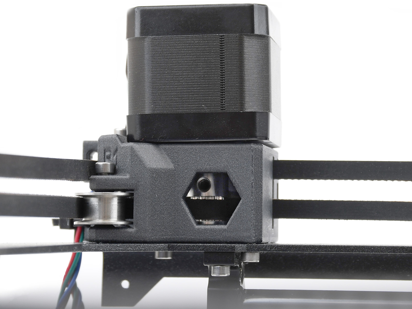 | 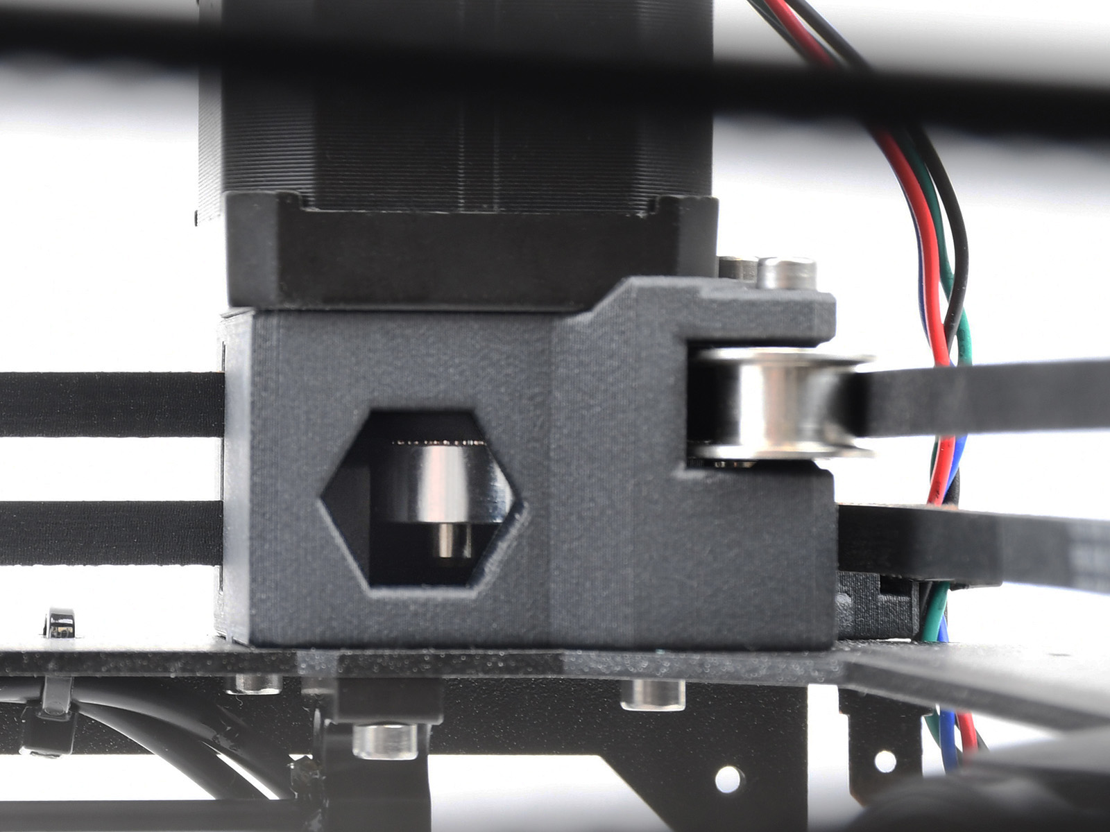 |
| Y-motor pulley | X-motor pulley |
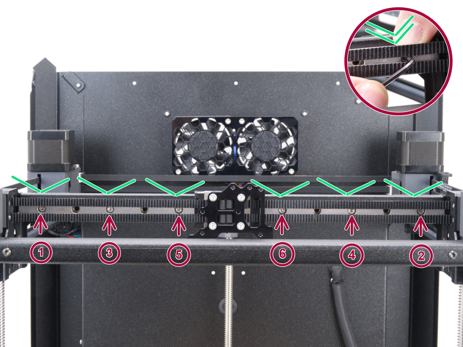
If none of the items mentioned help, loosen the six screws holding the X-axis linear rails slightly (one to two turns), let the rail drop down, and tighten them again in the correct order.
Z Alignment Calibration
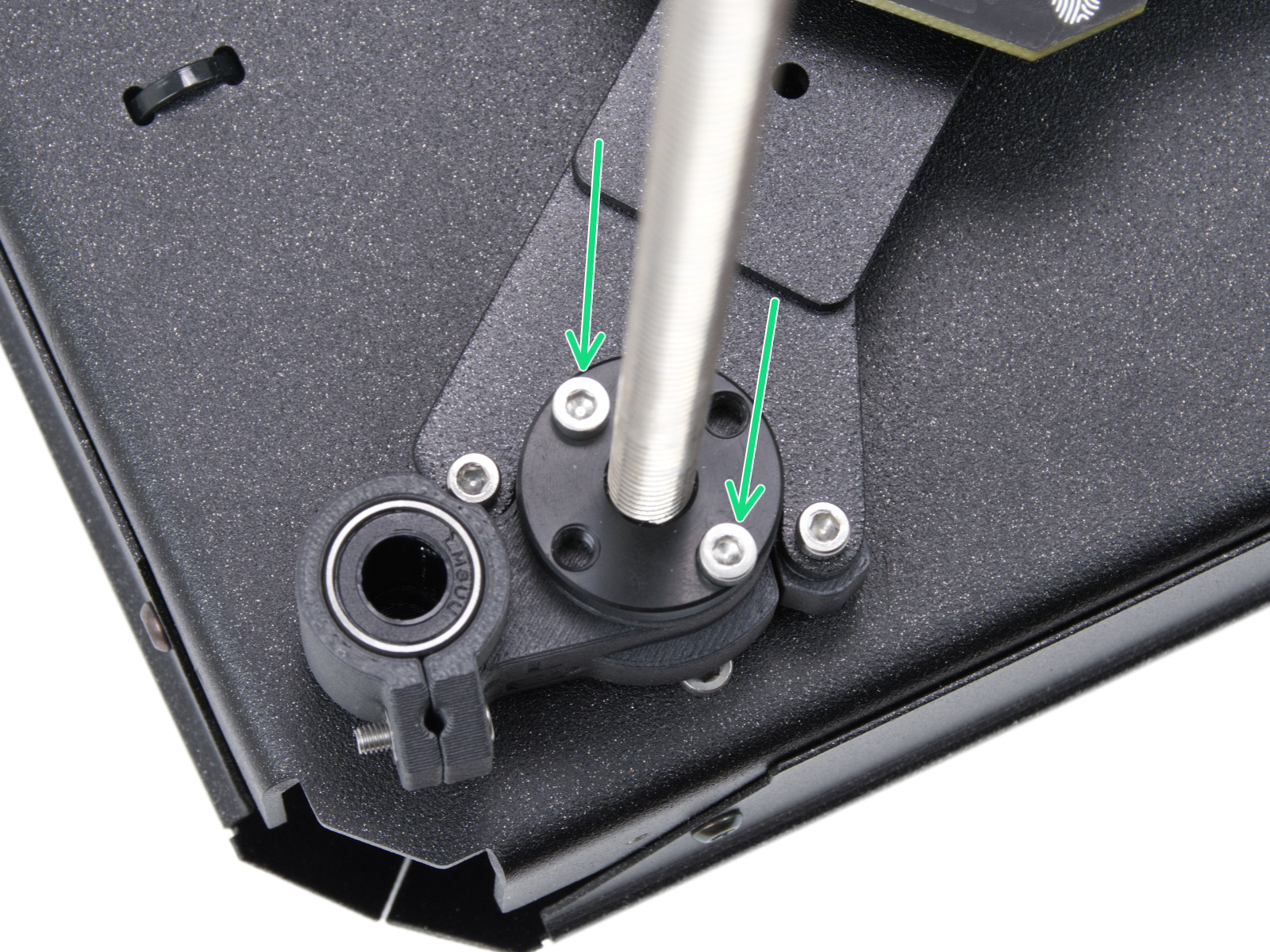
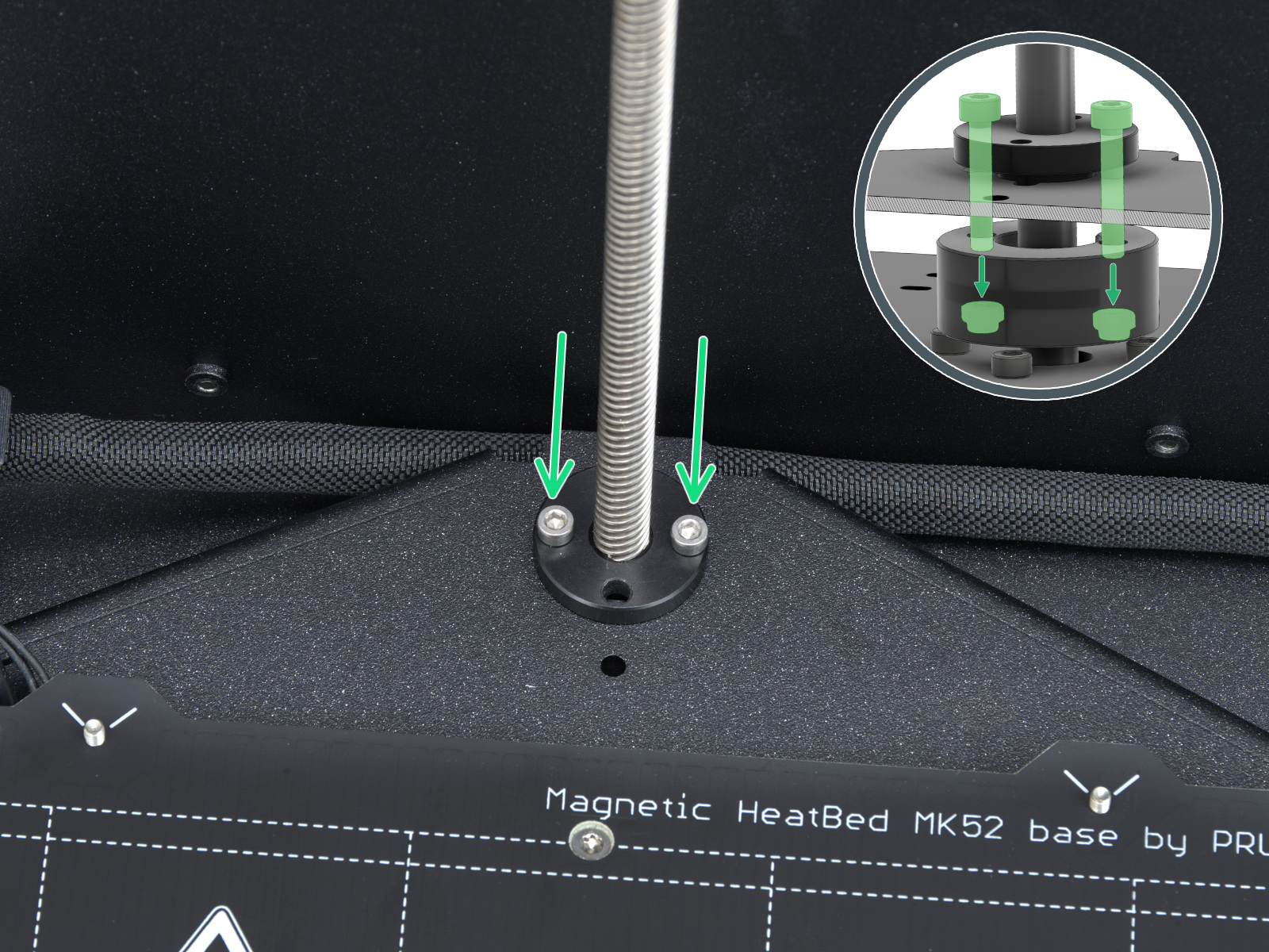
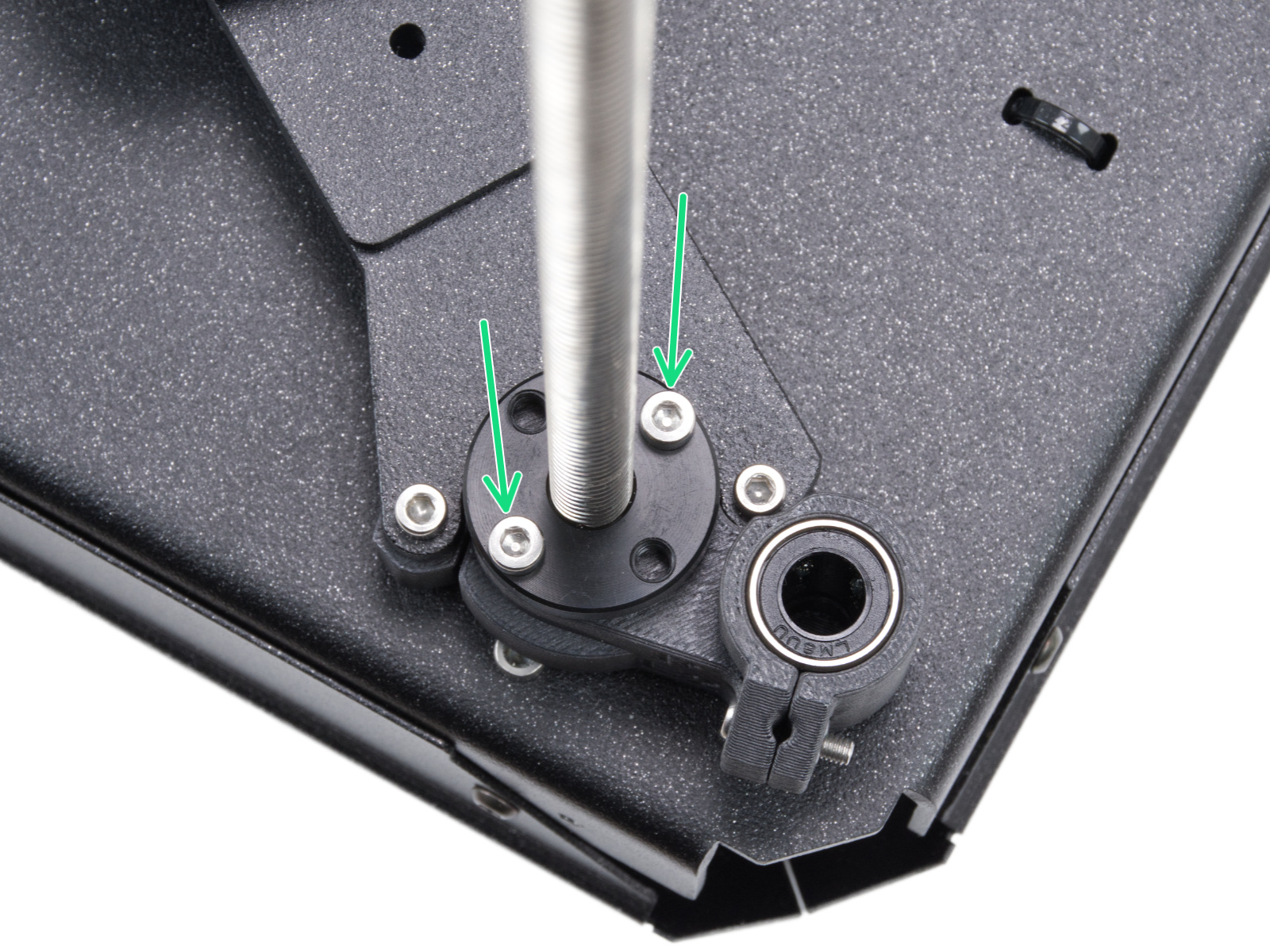
This part of the calibration will move to align the three motors on the z axis so that the heatbed is level. In case of any errors on this test, check the trapezoidal nuts on the motor threaded rods. For that, move the bed all the way down either by the menu in Control -> Move axis -> Move Z, or by turning the threaded rods on the z motors. Unscrew and remove the screws indicated in the image below. Move the nut along the threaded rod and see if the movement is smooth or not. When the trapezoid nut is still loose, try moving the motor threaded rod by hand (the printer needs to be powered off for that), and see if it turns easily.
 |  |  |
| Left side trapezoidal nut | Rear motor trapezoidal nut | Right side trapezoidal nut |
Loadcell test
A functioning loadcell is fundamental for the Prusa CORE One/+ to detect that the nozzle is close enough to the steel sheet for printing, and to avoid damage that would be caused by the nozzle digging into the steel sheet.
- Make sure that the loadcell is correctly connected to the LoveBoard.
- Make sure that the surface the printer is on is as stable as possible: any form of vibration propagated to the surface under the printer, or a not fully stable surface under the printer, might cause a false reading on the loadcell, causing it to fail the selftest.
- Check if the hotend is not moving and is inserted all the way.
 |  |
 | |
Heaters test
The selftest can determine a fault during the heating of a component, and the affected component.
Heat the affected component under LCD Menu -> Control -> Temperature, heat up the part that failed the selftest, and see if any error appears. If it does, the error should have a QR code that redirects to the article that describes how to troubleshoot that particular error.
Filament sensor
The Prusa CORE One/+ is equipped with two filament sensors: the first one is located on the side, close to the input of the PTFE tube where you feed the filament. The second one is located in the Nextruder.
Both filament sensors are necessary for the correct filament retraction. When the sensor on the side detects that the filament has run out, the filament will be retracted in time.
The printer prompts you to load the filament into the extruder to test the sensors. During the selftest, the two sensors is shown on the bottom of the screen. In case either of the sensors is not triggered:
- Make sure that the extruder filament sensor is correctly connected to the LoveBoard.
- Make sure that the side filament sensor is correctly connected to the xBuddy extension board.
- Check the cable of the side filament sensor for any damage.
- If the side sensor is presenting an issue, check if the lever is not overtightened.
|  |
 |  |
13 comments
Once that is set, you have to go into the menu and do the manual belt tuning. Rather than follow the on-screen advice (which said my belts were fine) I set the dial to 95 Hz and then adjusted the tension screws on both sides until both belts were vibrating like crazy in resonance. They should be moving around 5mm or so (towards and away from you, very rapidly, almost a blur), quite a lot more than you'd think. When you adjust one side it throws off the other side, so it takes a lot of back and forth to get them both vibrating by that amount at the same time. When you think you have it, briefly touch the belts to stop them from moving then when you move your finger away, they should both start vibrating like crazy again within a second or so.
Once this happens, finish the test without making any further adjustments (just set the X and Y axes to the same 95 Hz or whatever value you picked) and then hopefully the homing function will work.