English
Login
3D printers
Materials
Parts & Accessories
For Business
Software
3D Models
Community
Help
Courses
Blog
Company
Support
Original Prusa i3 MK2S
Original Prusa i3 MK2 kit assembly
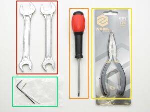
2. Y-axis assembly | Get the necessary tools
1. Get the necessary tools
Step 1 of 44 (Chapter 2 of 9)
Contents
Comments
⬢
13/17mm spanners
⬢
3.6mm flathead screwdriver
⬢
Needle-nose pliers
⬢
2.5 and 1.5mm Allen key
Loading...
Next
Contents
Original Prusa i3 MK2 kit assembly
1. Introduction
2. Y-axis assembly
Get the necessary tools
3D printed parts
Assemble the Y-axis rods
Assemble the Y-axis stage rear
Assemble the Y-axis stage front
Fully assemble the Y-axis stage
Preparing for Y-axis stage
Tighten the sides to the y-axis stage
VIDEO for step 8
Identifying the length of rods
Adjust the length of the Y-axis stage
VIDEO for step 11
Marker identification
Correct bearing orientation
Assemble the Y-carriage
Tighten Y-carriage zipties
Assembly of the Y-idler
Tighten the Y-idler
Y-axis motor
Y-endstop
Y-endstop cable guide
Assemble the Y-belt holder
Assemble the Y-carriage rods
Assemble the Y-axis stage
Tighten the zipties on the Y-axis stage
Y-belt holder nuts
Assemble the belt on Y-axis part 1
Assemble the belt on Y-axis part 2
Assemble the Y-motor pulley
Y axis belt placement
Loosening the motor
Tighten the Y-axis belt part 1
Tighten the Y-axis belt part 2
Tensioning the belt
Video for steps 27-34
Adjust the Y-idler
Adjust the Y-motor-mount part
Tighten the screws in the pulley
Y-axis stage cable management
Levelling the Y-axis
Secure the axis feet
The Y-Endstop check
Double check Y-carriage!
All done!
3. X-axis assembly
4. Z-axis assembly
5. Extruder Assembly
6. LCD assembly
7. PSU & Heatbed assembly
8. Electronics assembly
9. Preflight check
Comments
Log in
to post a comment
No comments