日本語
Login
3Dプリンター
マテリアル
部品 & アクセサリー
法人向け
ソフトウェア
3Dモデル
コミュニティ
ヘルプ
コース一覧
ブログ
会社概要
サポート
Original Prusa MK4
プリンターメンテナンス
How to replace xLCD (MK4/MK3.9/MK3.5) | 組み立てを始める
1. 組み立てを始める
ステップ 1 / 19 (章 14 / 14)
内容
コメント
難易度
ほどほど
利用可能な言語
組み立てを始める
内容
プリンターメンテナンス
フィラメントガイドアドオン (MK4S/MK4)
ネクストルーダーV6ノズルアダプター(MK4/MK3.9)の取り付け方法
Prusaノズルの交換方法(MK4/MK3.9)
Loveボードの交換方法 (MK4S/MK4/MK3.9S/MK3.9)
銀のPSUから黒いPSUへの交換方法
ホットエンドヒーターの交換方法 (MK4/MK3.9)
ホットエンドサーミスターの交換 (MK4/MK3.9)
ホットエンドファンの交換方法 (MK4/MK3.9)
xBuddyボードの交換方法 (MK4/MK3.9/MK3.5)
プリントファンの交換方法 (MK4 / MK3.9)
ホットエンドアッセンブリの交換方法 (MK4/MK3.9)
How to replace a Heatbed Thermistor (MK4/S, MK3.9/S, MK3.5/S)
How to replace a hotend heatsink (MK4 / MK3.9)
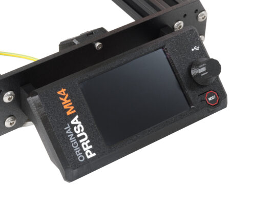
How to replace xLCD (MK4/MK3.9/MK3.5) [進行中の翻訳]
組み立てを始める
はじめに
MK4: xLCD versions (part 1)
MK4: xLCD versions (part 2)
準備
Tools necessary for this chapter
xLCDの取り外し
xLCD Disassembly (part 1)
xLCD Disassembly (part 2)
Parts preparation (part 1)
Parts preparation (part 2)
xLCD assembly (Version upgrade)
Assembling the xLCD-support-right
Installing the Faston connector
Assembling the xLCD-support-left
Connecting the cables
Attaching the knob
xLCDアセンブリの取り付け
完了
コメント
ログイン
してコメントを投稿する
コメントなし