In many cases, we need to decide whether a component is faulty or just wrongly installed. There are also situations where we need to decide exactly which component should be replaced. We are using the multimeter (multitester) for checking the continuity of wires, measuring the resistance values of heaters, thermistors, and fuses, and measuring the voltage coming from the PSU and going to the heaters.
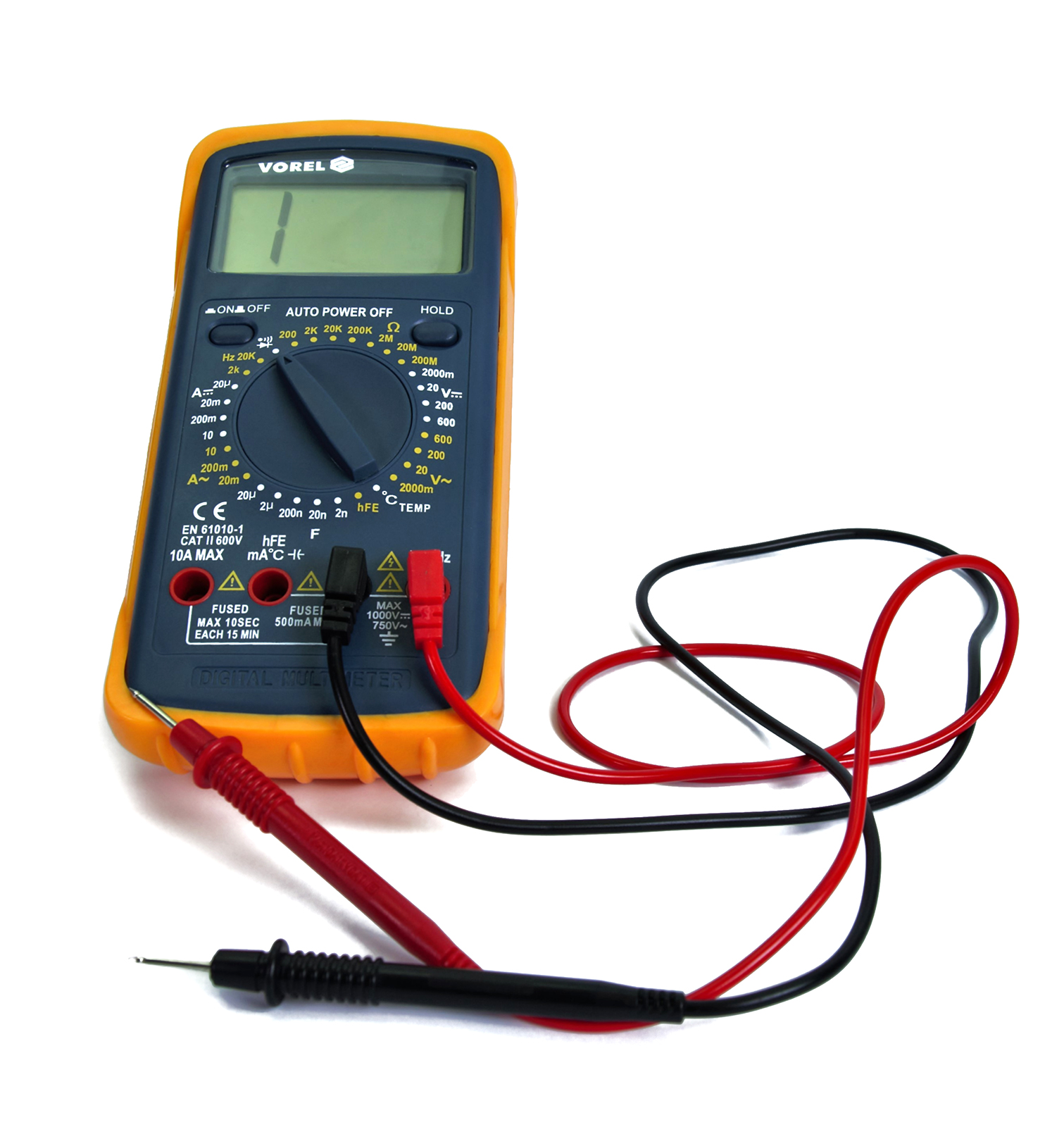
If you don't have a multimeter, you can consider one that is similar to what is depicted below. The device does not have to be expensive. 10-15 USD/EUR will get you something that does the job just fine.
Before taking the multimeter, make sure to run the printer selftest.
Multimeter setup
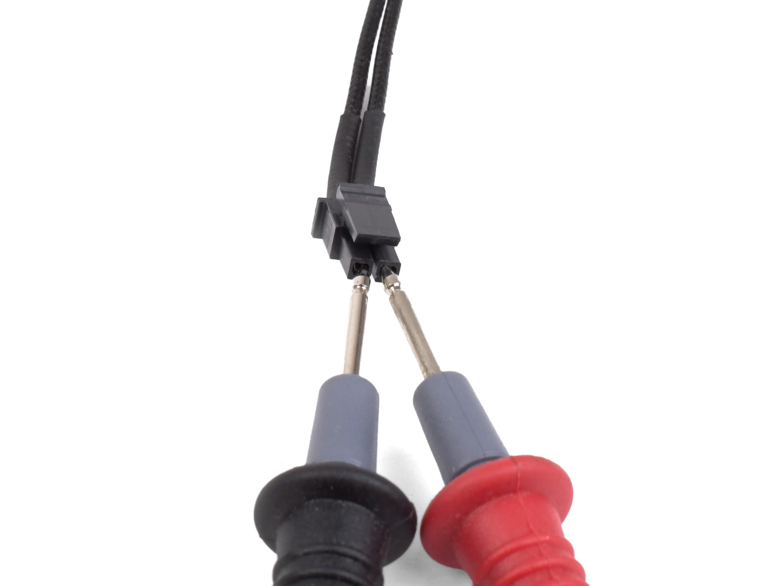
To get started, we first have to properly connect the two measurement probe cables to the multimeter.
- The black lead goes into the COM port.
- The red lead goes into the port for Volts (V), Ohms (Ω), and Frequency (Hz).
Then we have to set the correct voltage or resistance range on the multimeter, depending on which component you are testing. For example, you can not measure 100K Ohm (Kilo=1000) if your meter is set to only 200 Ohm. You must set it to 200 K.
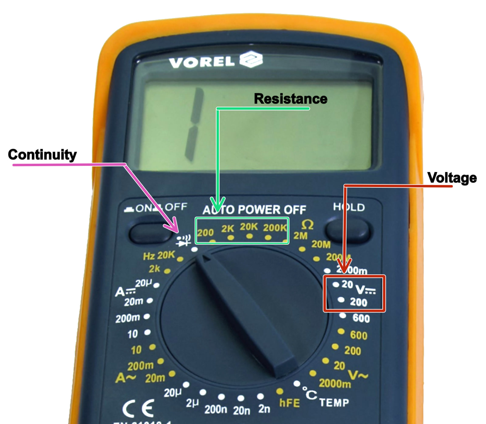
Reference for multimeter settings
Resistance setting:
- For all thermistors, set the resistance value to "200K" Ohm (green arrow), since the thermistor should have around 100 K.
- For all heaters, set the resistance value to "200" Ohm (green arrow), since heaters read between 1 and 20 Ohms.
Voltage setting:
If measuring the voltage going to a heater or to the printer itself it is important to remember that the MK2/S and MK2.5S are 12V systems, while the MK3S is a 24V system.
- For a 12V system, set the meter to "20" volts (red arrow).
- For a 24V system, set the meter to "200" volt (red arrow).
Continuity setting:
The setting is indicated by the purple arrow and will display 0 and give a beep if the two probes connect, either by touching or connected by a cable. This is to test if a wire is broken or not.
Where to measure
Print head
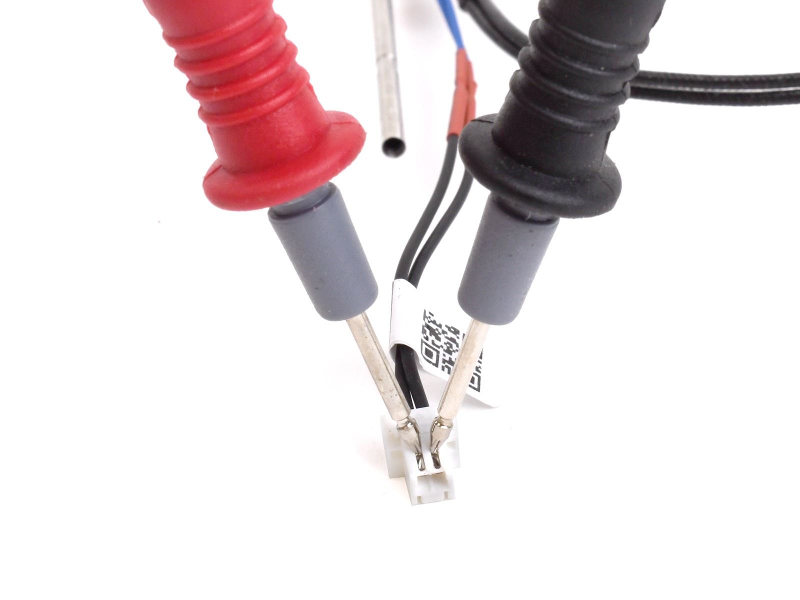
For every component, there are several options, our main focus will be on the connectors. The measurement appears on the multimeter LCD as soon as the measurement probes touch the component.
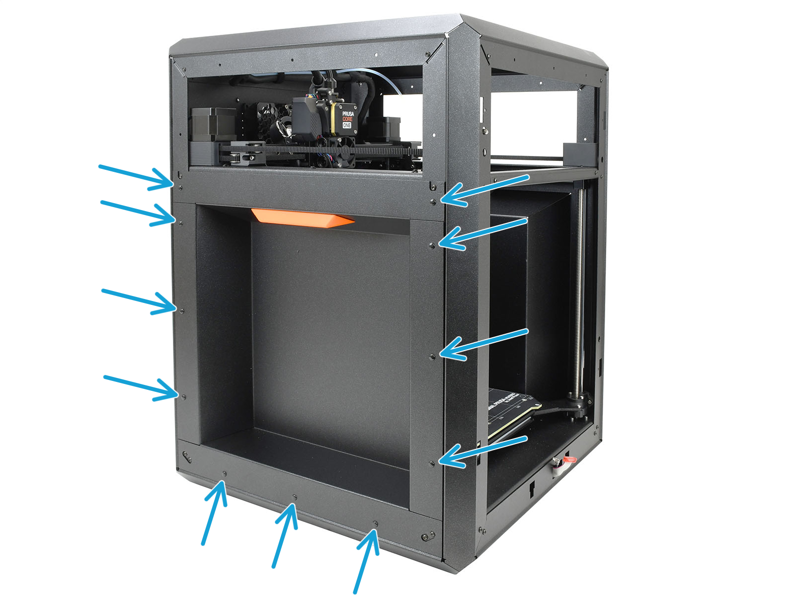
On the MK2/S, MK3/S/+, and MINI/+, the print head thermistor and print head heater are connected to the main board. To access them, open the screw that holds the electronics box closed.
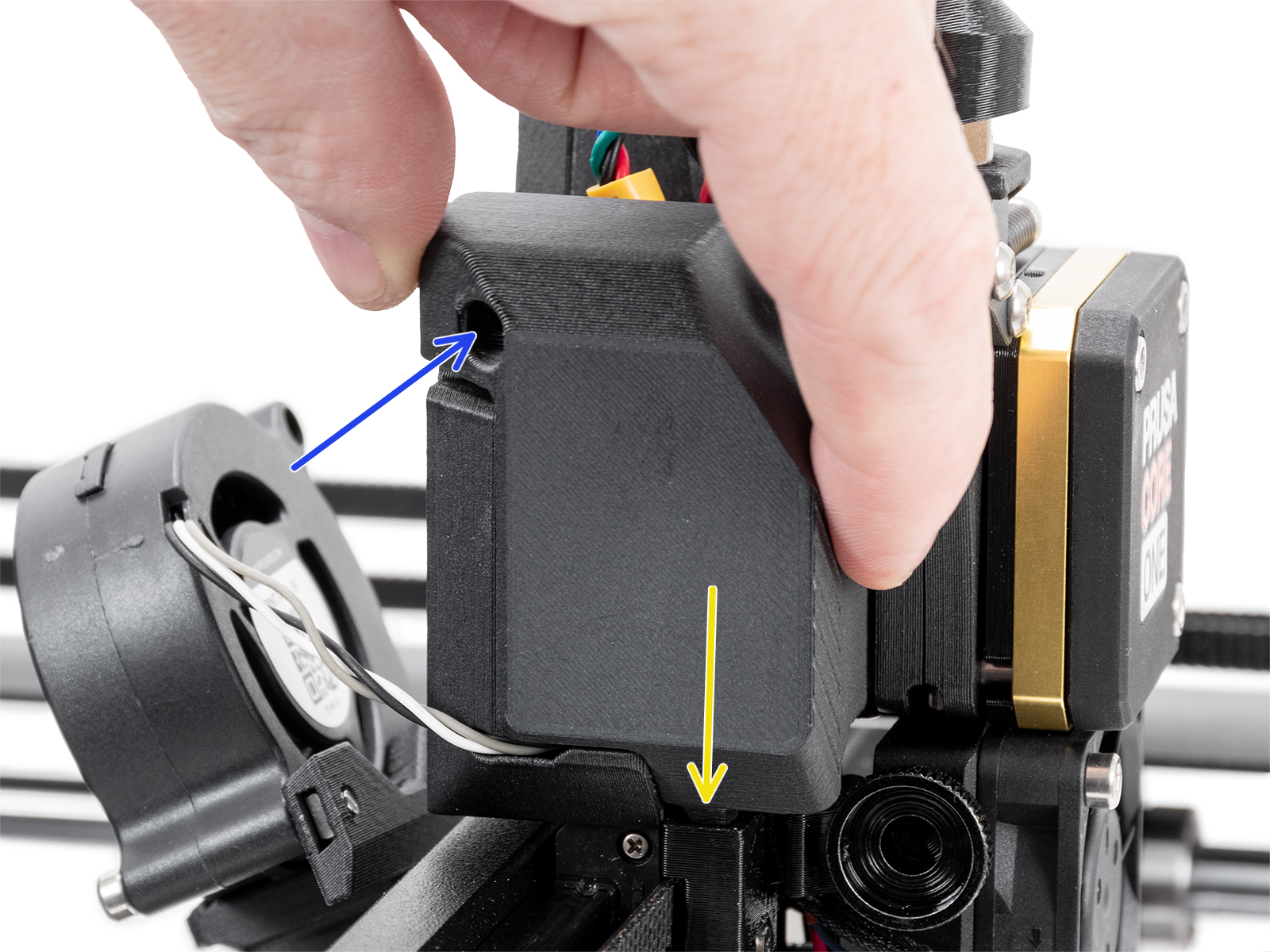
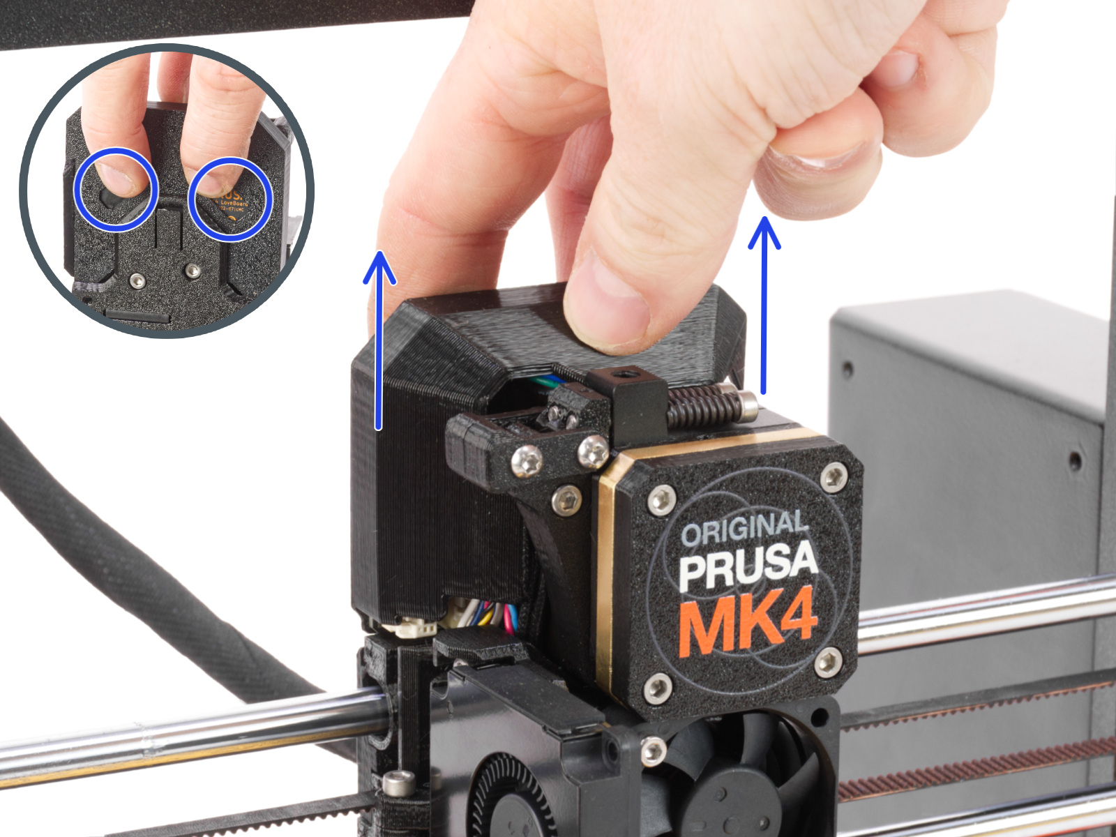
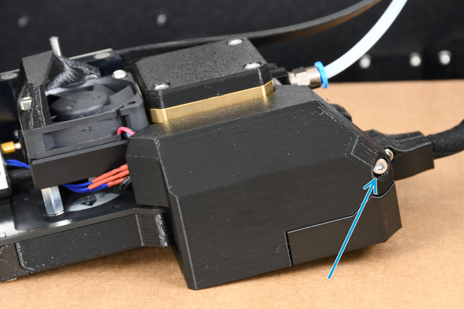
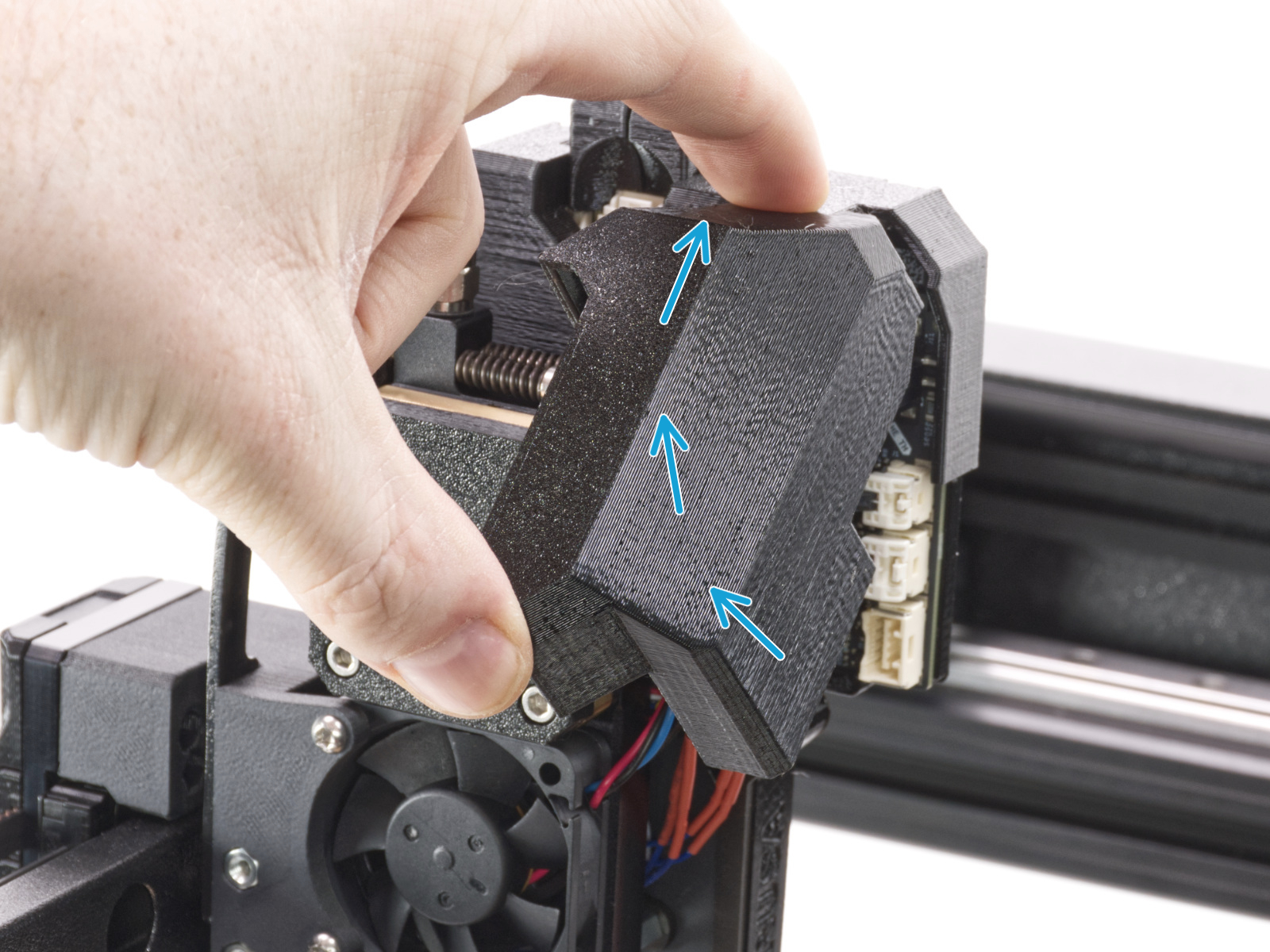
On the CORE One, MK4, and XL, the two components are connected on the board located on the extruder, respectively LoveBoard and the Dwarf Board. To access the connectors on each extruder, do the following:
- CORE One: open the screw that holds the print head cover left and detach it.
- MK4/S: slide up the Loveboard-cover.
- XL Multi-Tool: open the screw that holds the dwarf cover door.
- XL Single-Tool: lift the dwarf cover door.
To obtain the correct and relevant values, this is where you need to apply the probes:
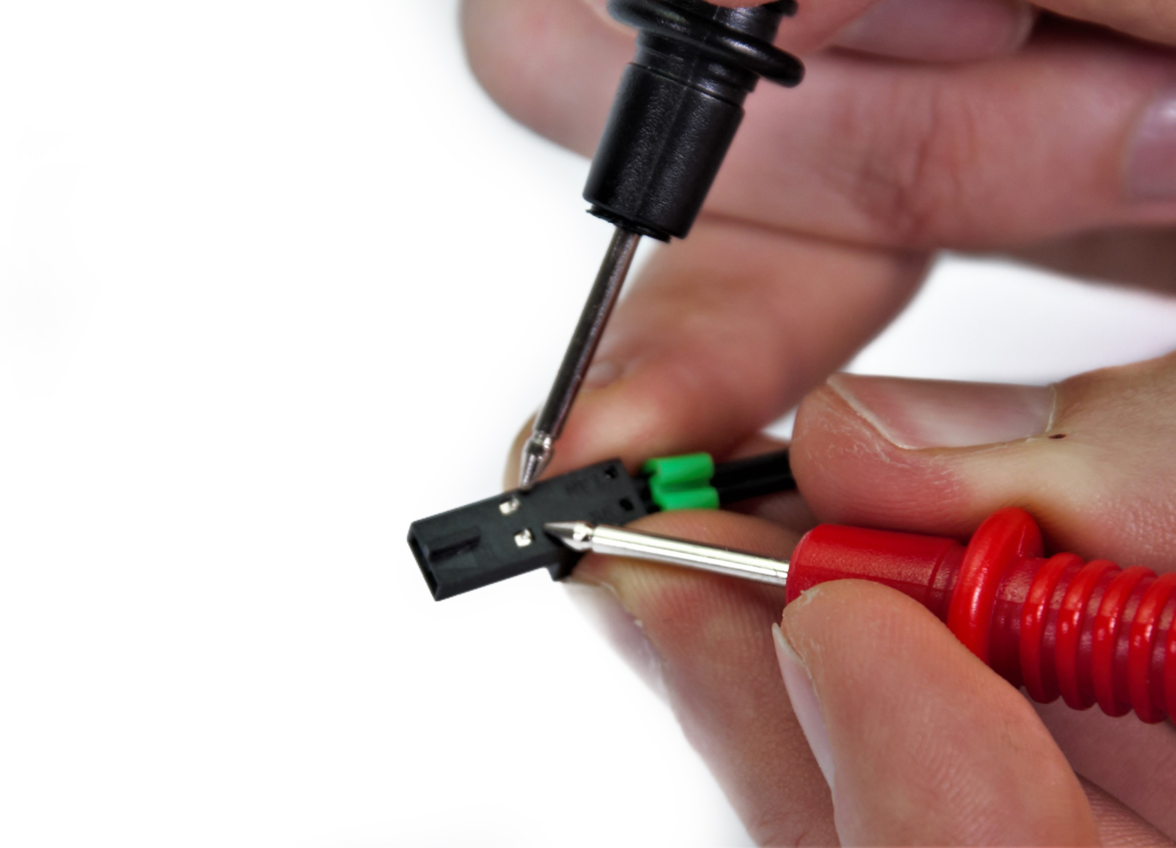 | 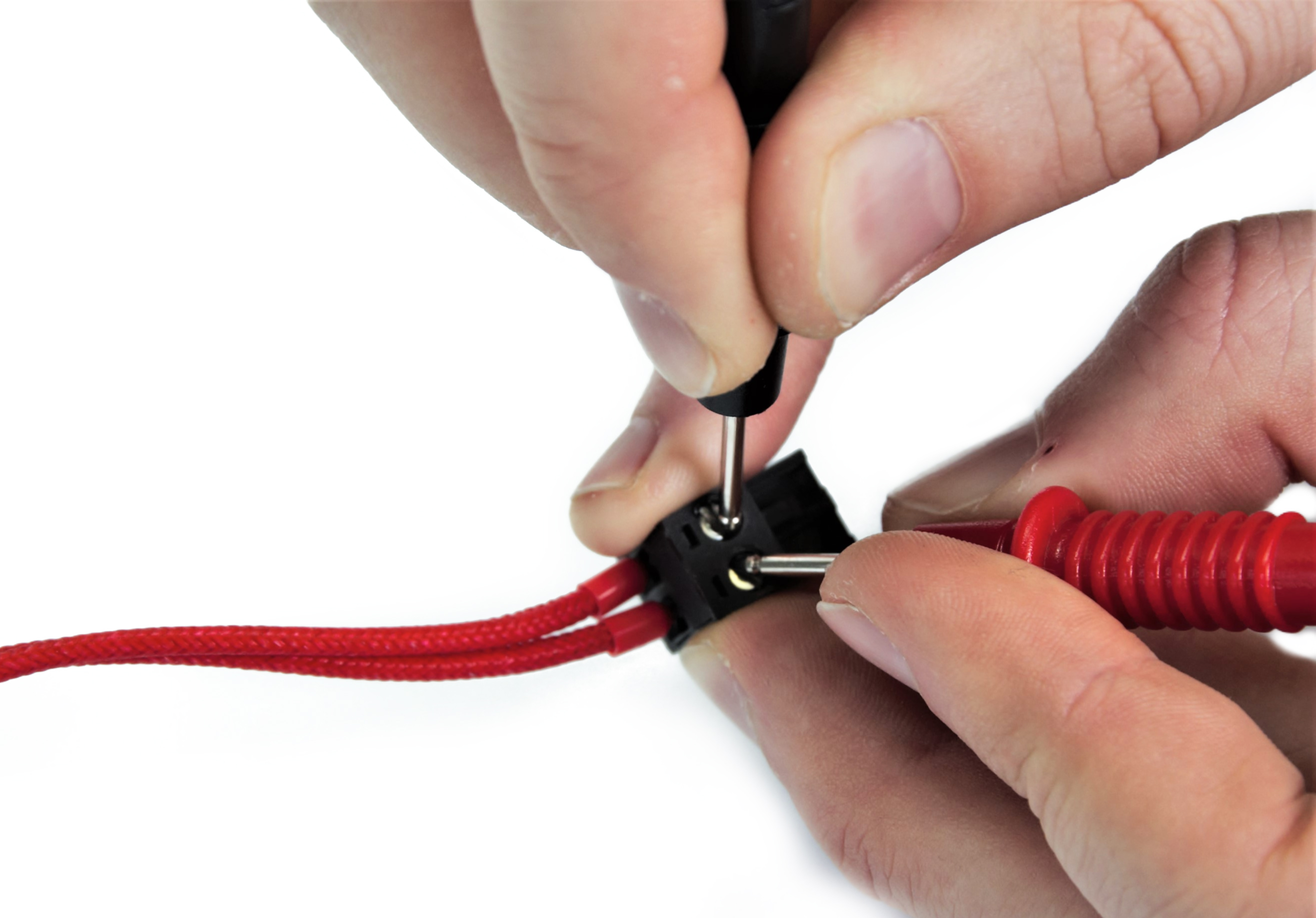 |
| Metal inserts in plastic connectors (Einsy RAMBo, Mini RAMBo, Buddy board) | Heater: screws holding the cables in the connector (Einsy RAMBo, Mini RAMBo, Buddy board) |
 |  |
| Hotend heater (LoveBoard) | Hotend thermistor (LoveBoard) |
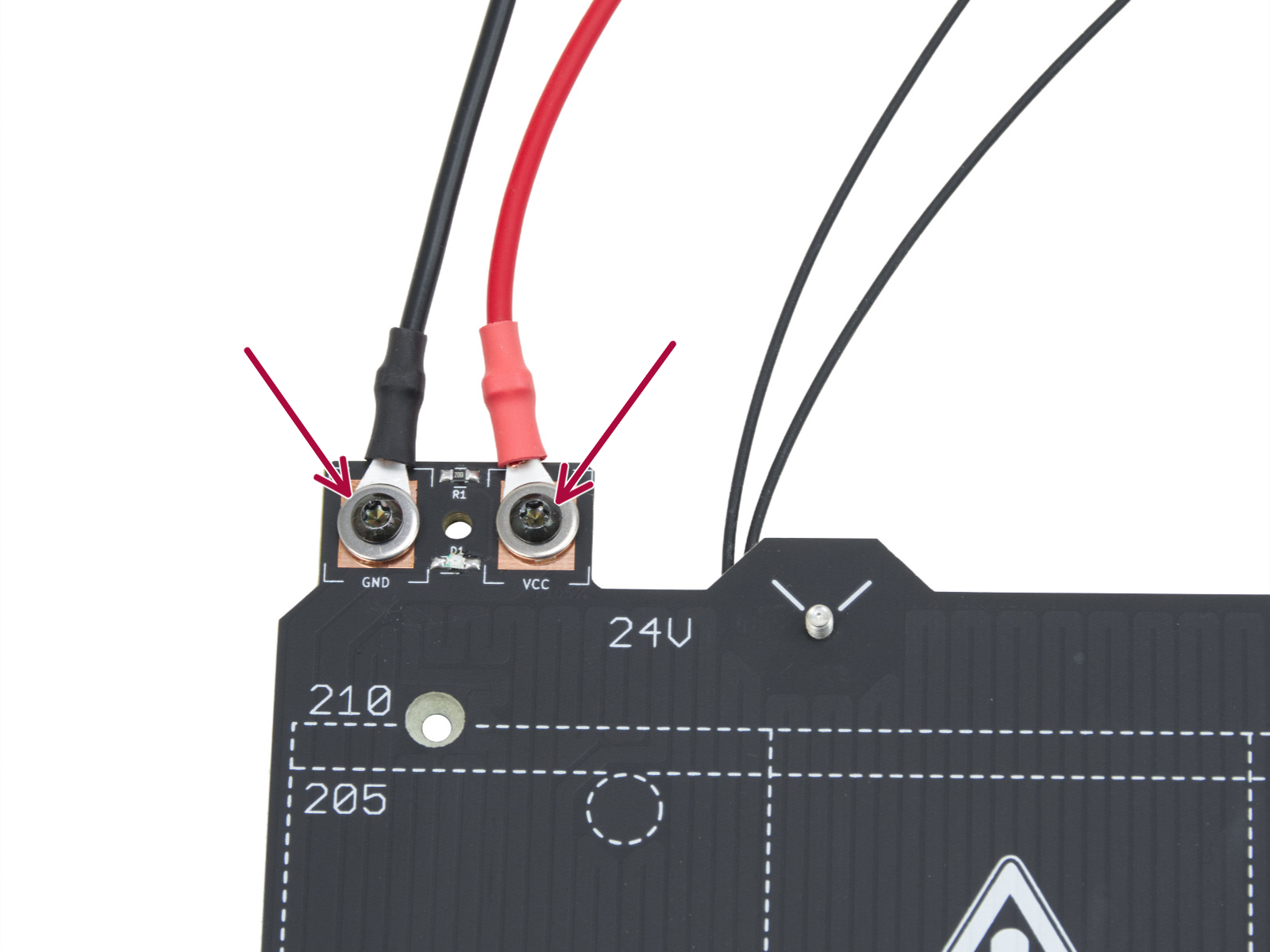
Heatbed
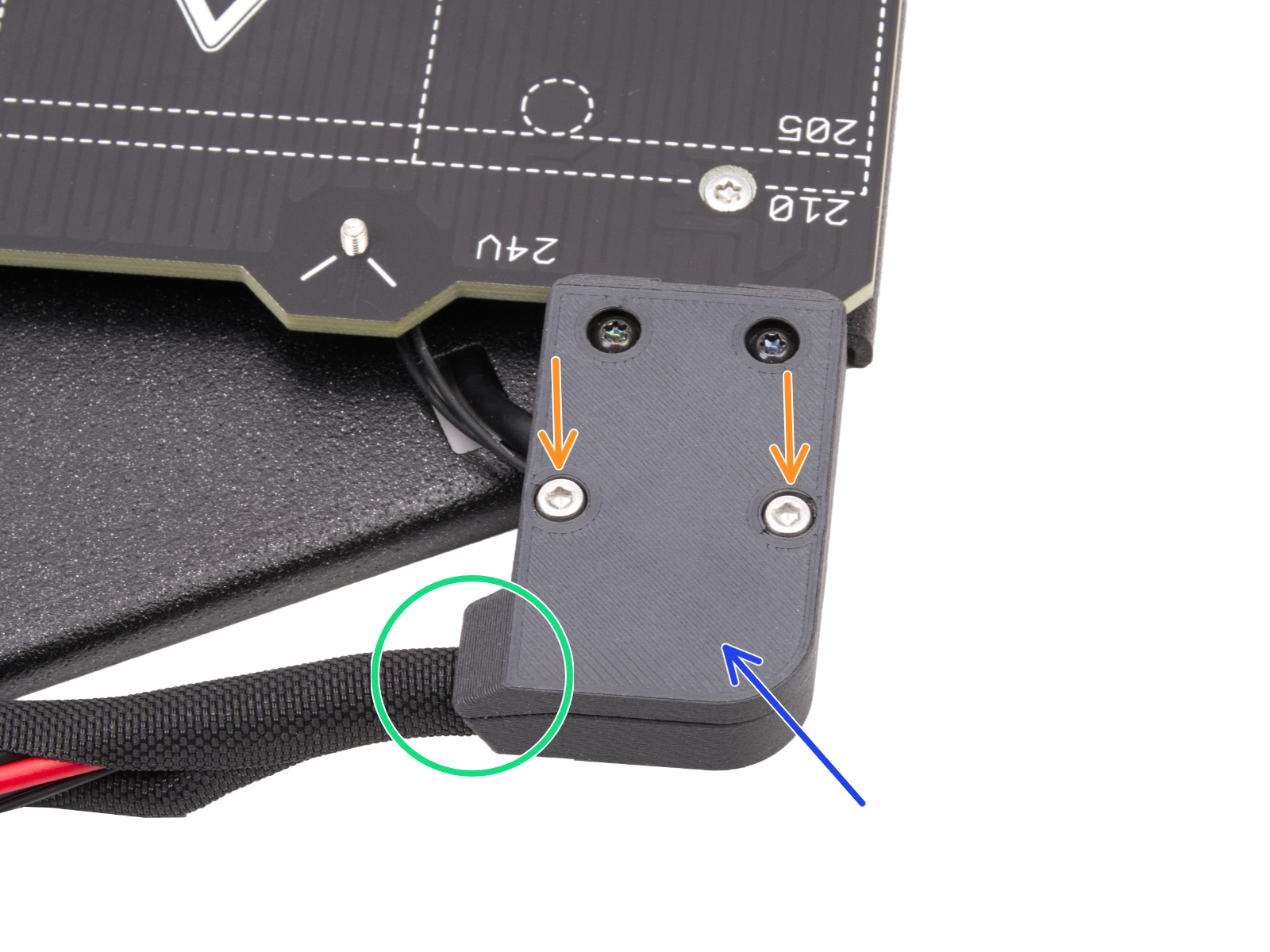
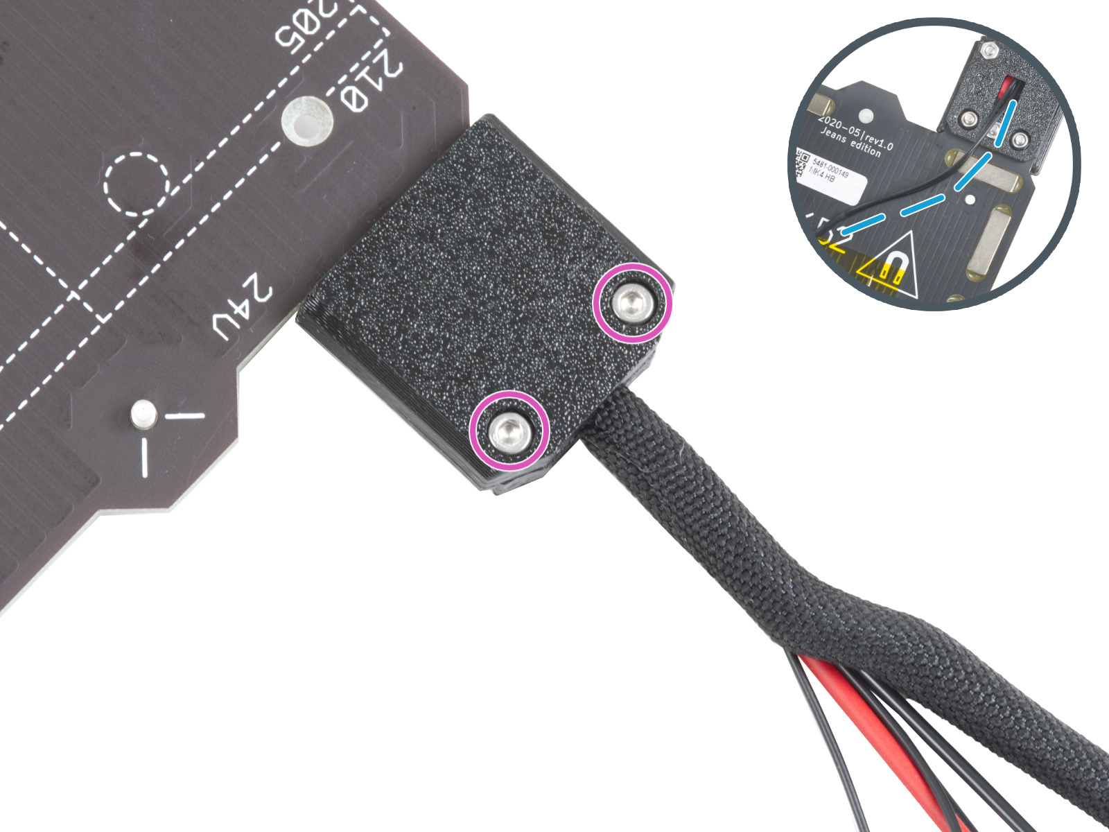
To access the heatbed cables, remove the printed part that is covering them, typically attached by one or two bolts.
 |  |
| CORE One/+ | MK4/S |
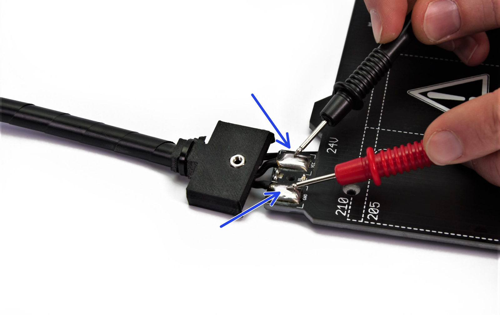
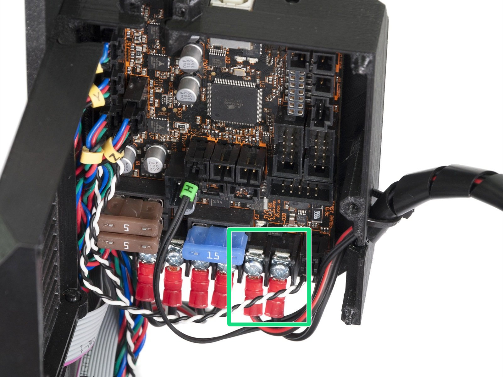
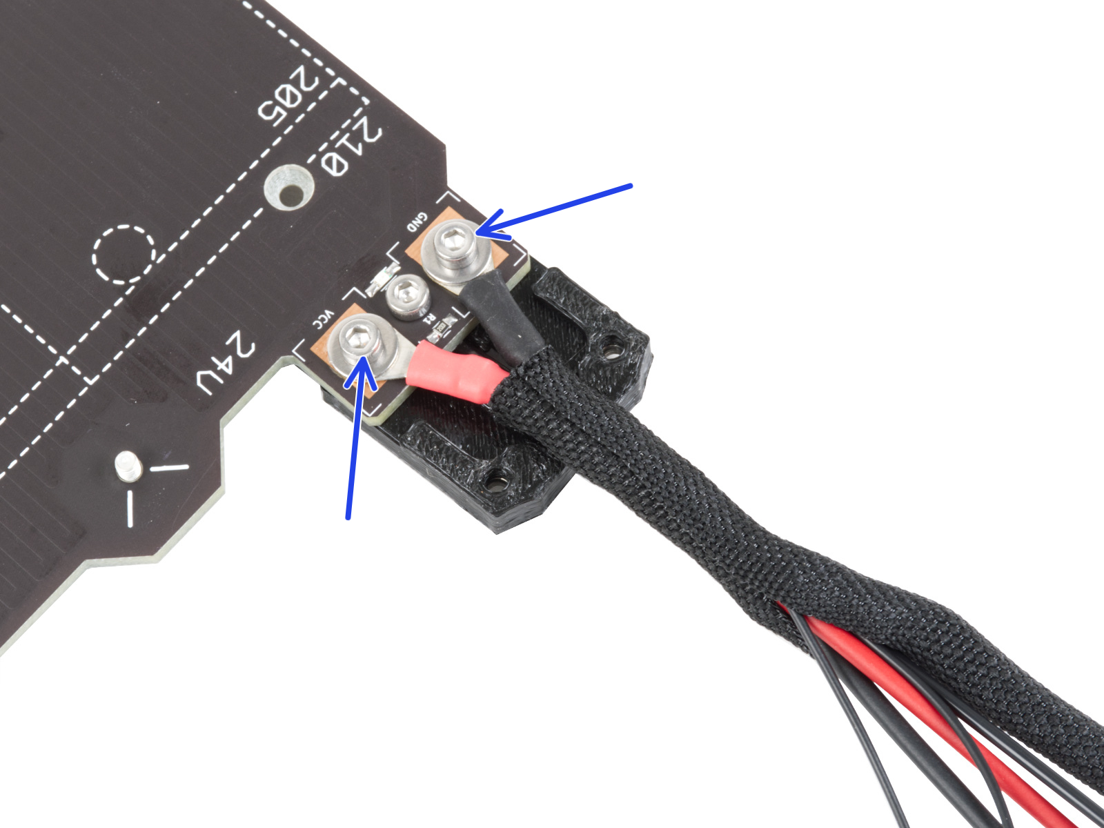
You can measure the resistance on the solder pads/screws holding the wires on the heat bed (blue arrows) or the ends connected to the mainboard (green square). You must remove the cables from the board before you do the measurement.
For the CORE One, it might be useful to remove the left side panel for easier access to the heatbed cables.
We do not recommend measuring the XL heatbed cables.
 |  |
| MK2/S and MK3 heatbed | MK2/S and MK3/S/+ board |
 |  |
| MK3/S/+, MK3.5/S, MK4/S, and MK3.9/S heatbed | MK3.5/S, MK4/S, and MK3.9/S board |
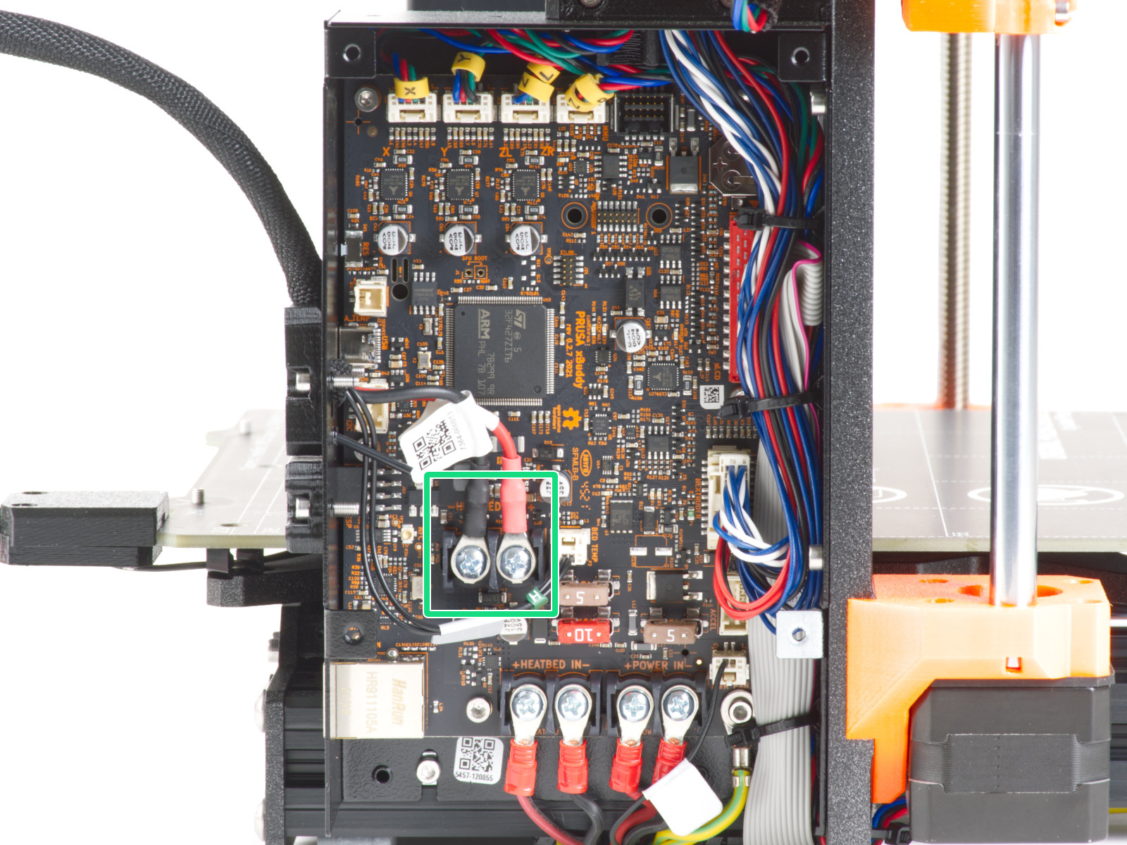 | |
| Heatbed Connector on xBuddy board | |
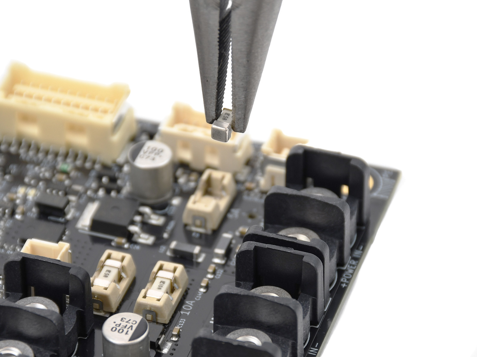
Fuses or wires
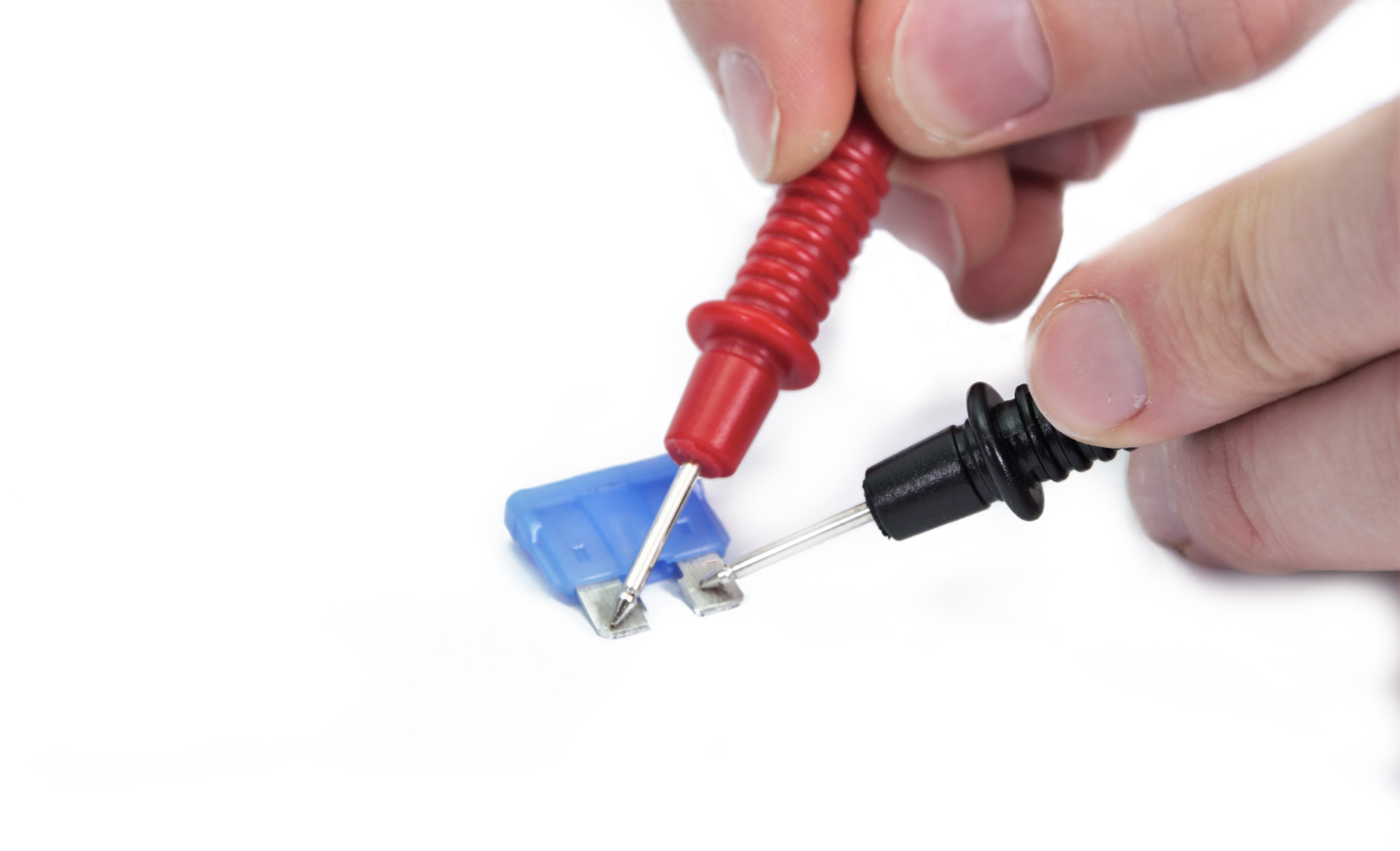
Fuses can be checked by using the continuity feature on a multimeter. The only thing that will be checked is whether the component is able to conduct signals or power.
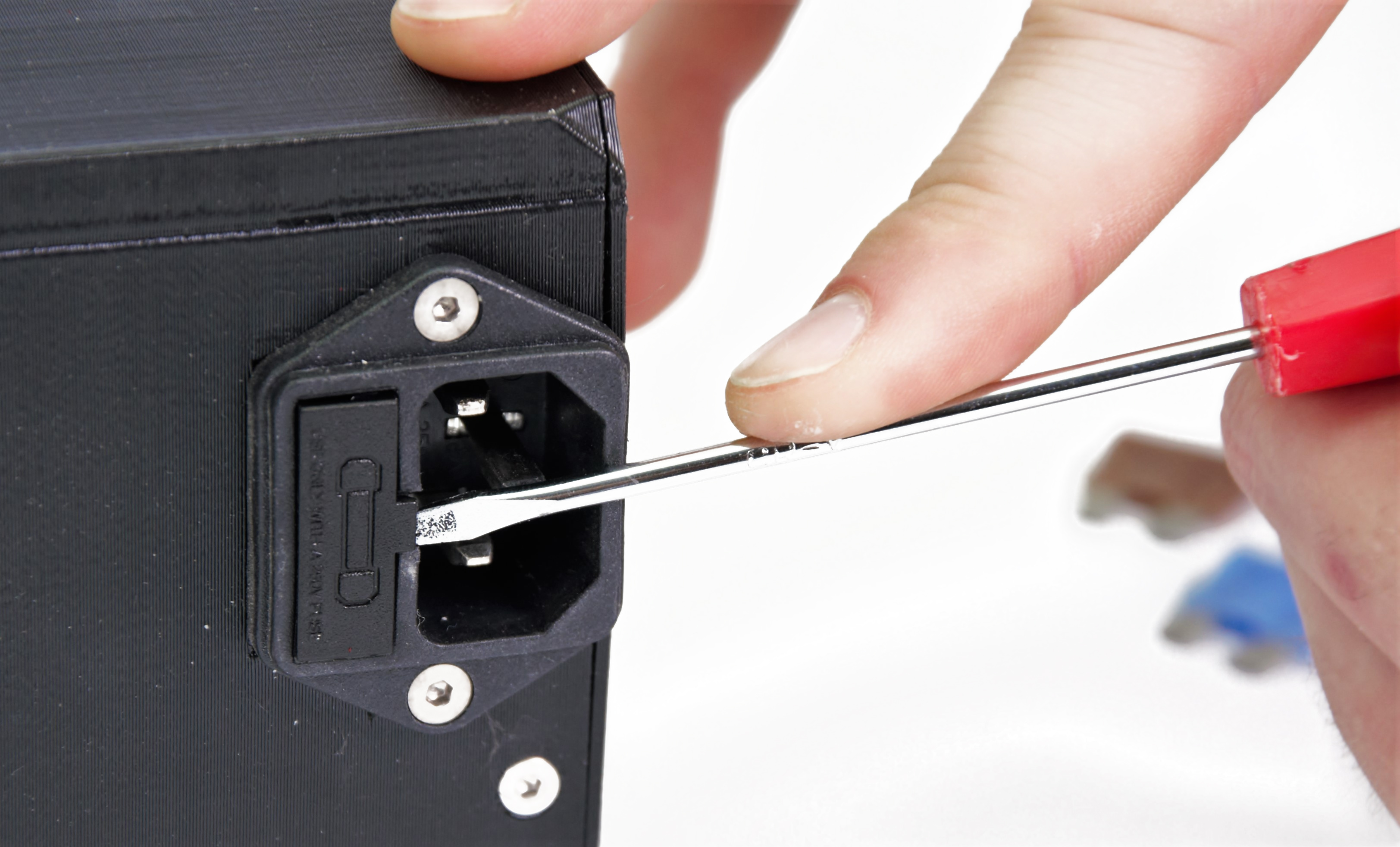
The blade fuses can be pulled out of the board by hand. The SMD fuses can be pulled with pliers. The fuse for the PSU can be taken out of the slot above the power cord by using a flathead screwdriver.
By touching each of the measurement leads of the multimeter to the other end of the fuse or wire, a signal (beep or 0 value on the multimeter screen) will indicate that the component is intact and therefore, should work.
 |  |
 | |
Resistance
To check if heaters are within their range of specified resistance, the following measurements can be done. For this measurement, the multimeter needs to be set to the lowest range, which includes 20Ω.
The measurement can be done on the screws in the connector for both the hot end heater and the heat bed. For the heat bed, it is also possible to probe the solder pads/screws holding down the cables. Please see the pictures above.
Heaters
|
MINI |
Hot end heater |
[12.3 Ω - 15.1 Ω] |
|
Heat bed |
[4.5 Ω - 6.5 Ω] | |
|
MK3/S/+, |
Hot end heater |
[12.3 Ω - 15.1Ω] |
|
Heat bed |
[2.0 Ω - 4.0 Ω] | |
|
MK2/S |
Hot end heater |
[3.1 Ω - 3.8 Ω] |
|
Heat bed |
[0.9 Ω - 1.1 Ω] |
Thermistors
To check if thermistors are within their range of specified resistance, the following measurements can be done. For this measurement, the multimeter needs to be set to the lowest range which includes 150 kΩ. Commonly, this is 200K on multimeters.
All thermistors are rated to be 100 kΩ at 25 °C. To be realistic, with a varying temperature between 20°C and 30°C, you can expect [125 kΩ - 80 kΩ].
Always check both thermistors to compare them. If they are different, one is probably faulty.
Voltage
In order to check if the correct voltage is being supplied to the heaters, the following measurements can be done. For this measurement, the multimeter needs to be set to the lowest range, which includes 24V.
The measurement can be done on the screws in the connector for both the hot end heater and the heat bed. For the heat bed, it is also possible to probe the solder pads/screws holding down the cables. In this case, the connectors have to be connected to the RAMBO.
For the MK4/MK3.9 and the XL, it is not possible to measure the voltage on the hotend heater because the connections are too small.
To measure, start preheating the printer to PLA and measure the component you are investigating.
The following values can be expected:
|
MINI |
Hot end heater |
[23V - 24.5V] |
|
Heat bed |
[23V - 24.5V] | |
|
MK3/S/+, |
Hot end heater |
[23V - 24.5V] |
|
Heat bed |
[23V - 24.5V] | |
|
MK2/S |
Hot end heater |
[11V - 13.5V] |
|
Heat bed |
[11V - 13.5V] |
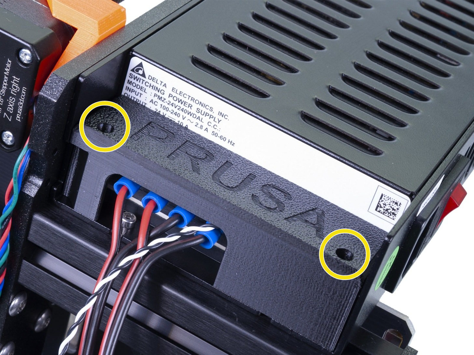
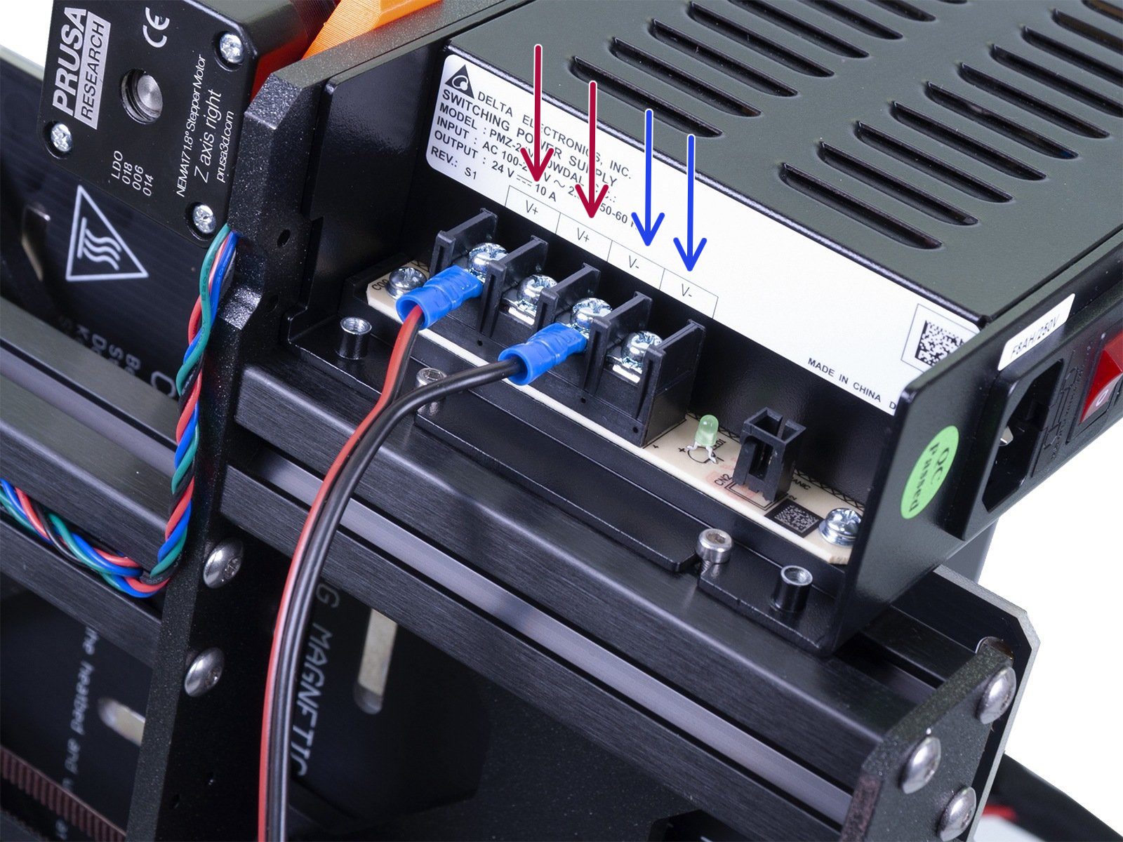
If you suspect the PSU is dead, and you have checked the external fuse, you can probe the terminals directly. Remove the two screws holding the cover (yellow circles) and you will have access to the power terminals.
VCC and ground (+ and -) are divided into two pairs, where the two left connectors are VCC (red arrows) and the two right connectors are ground (blue arrows). Measure one from each pair.
 |  |
10 comments
I made a test with a 10 Ohm resistor. Measuring directly gave me a value of 8.2 Ohm (way off the 5% accuracy). Using the method given in the article, I calculated a value of 10.02 Ohm. I also used to measure the resistor of the heat bed (MK4S) and I got 3.2 Ohm. Eventually newer multimeters are accurater, compared to mine being around 40 years old.
I suggest using above method for measuring resistances of the heat bed or hot end heater.
Hello. Please contact our support team for help.
Hello. Please talk with our support team for this issue. Thank you.