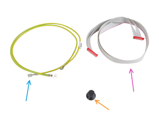
⬢以下のステップに向けて、下記の部品を用意してください。
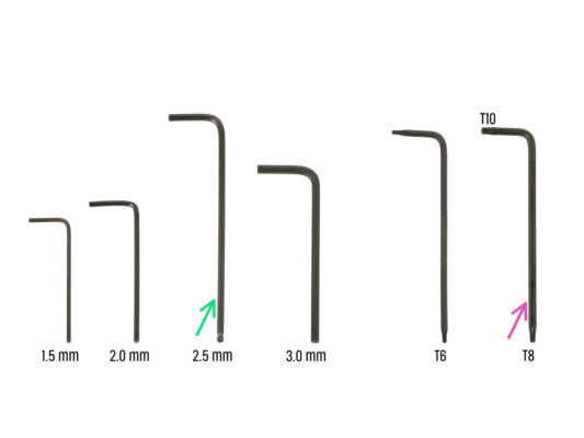
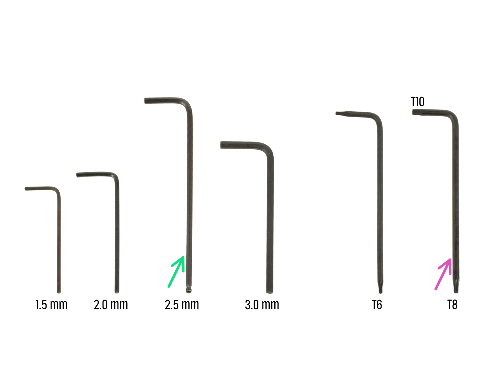
⬢2.5 mm 六角レンチ
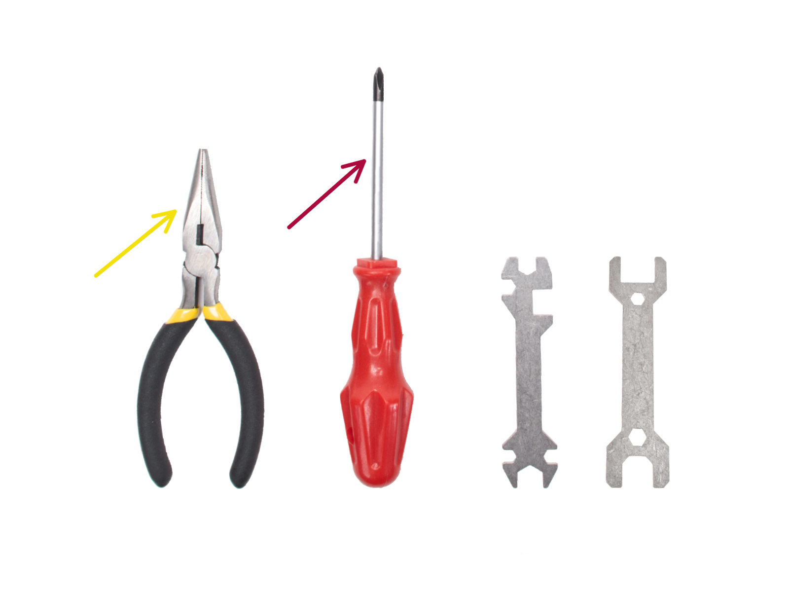
⬢結束バンドをカットするためのラジオペンチ
⬢T8/10 トルクス・キー
⬢プラスドライバー (1本)

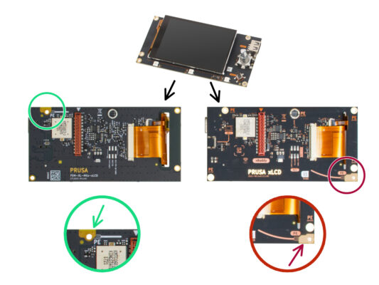


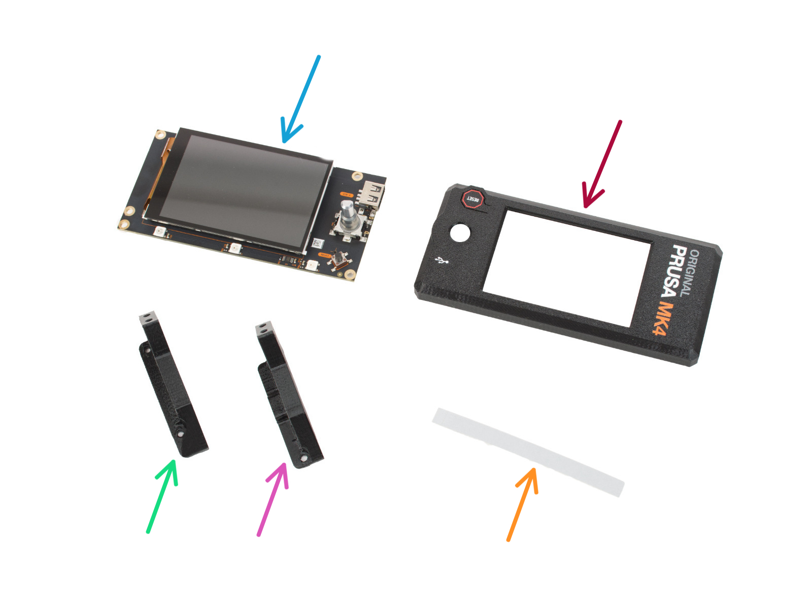

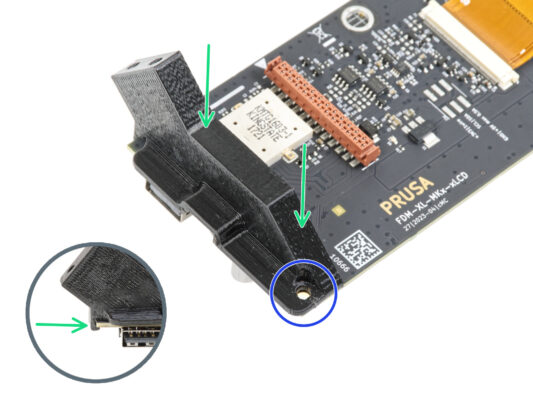
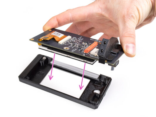


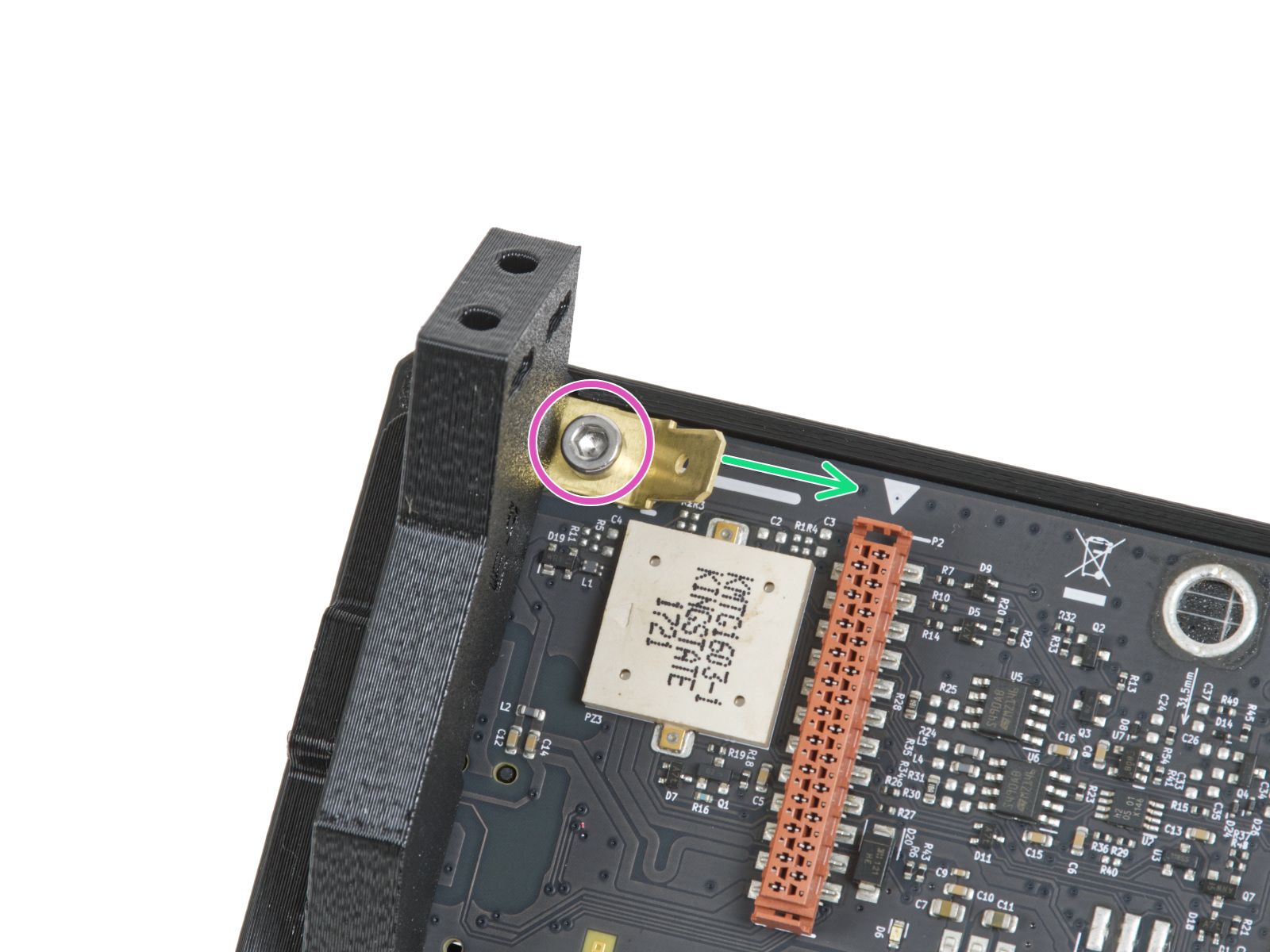


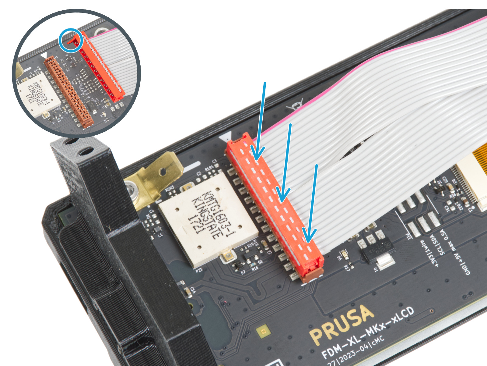
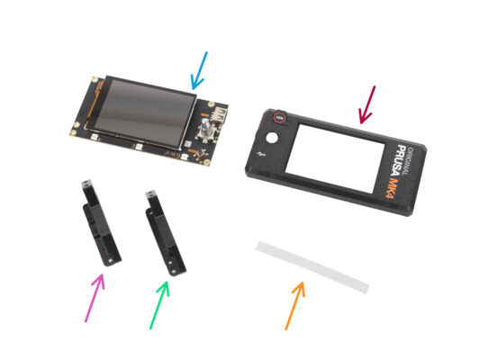
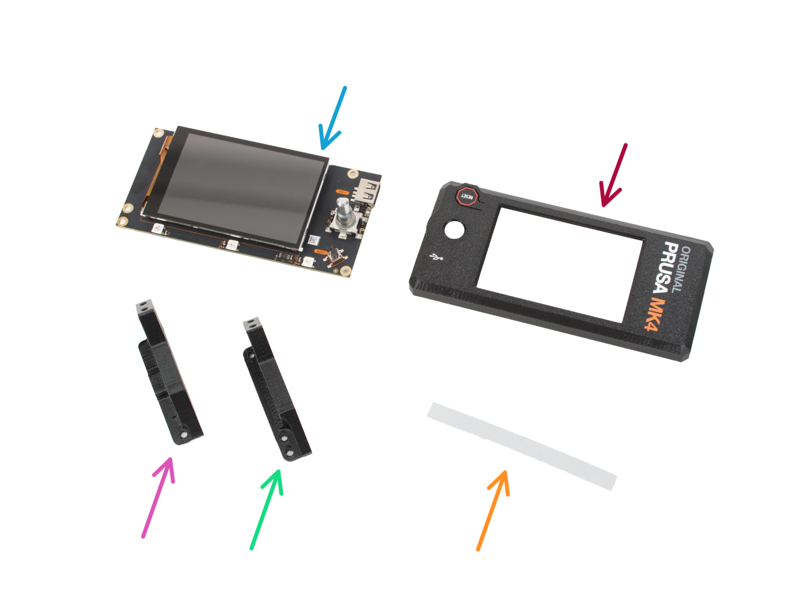


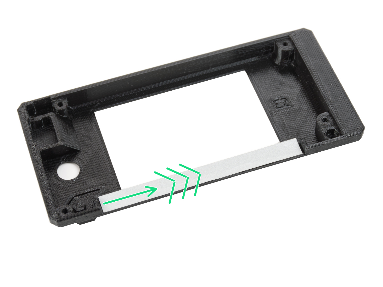
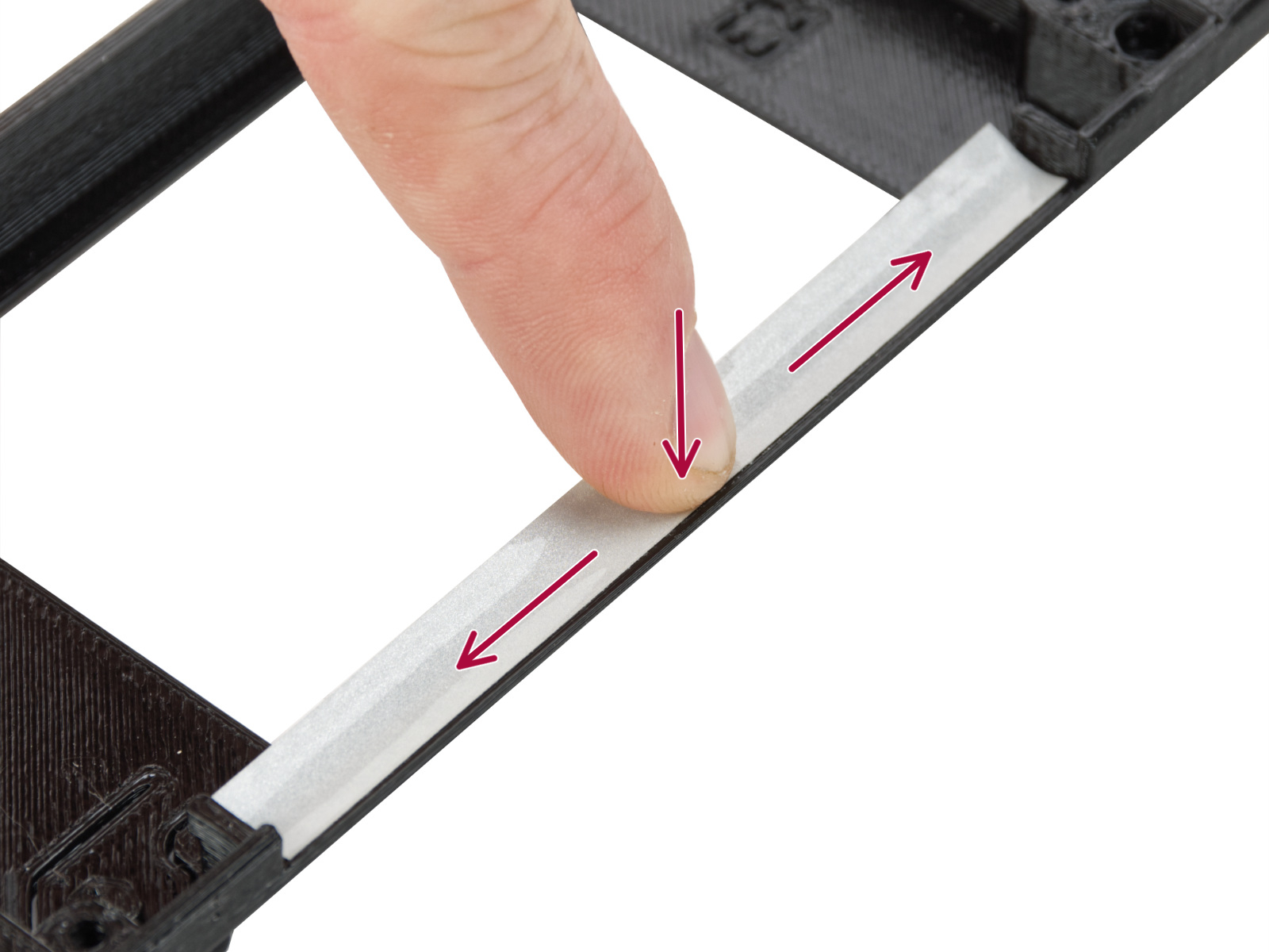


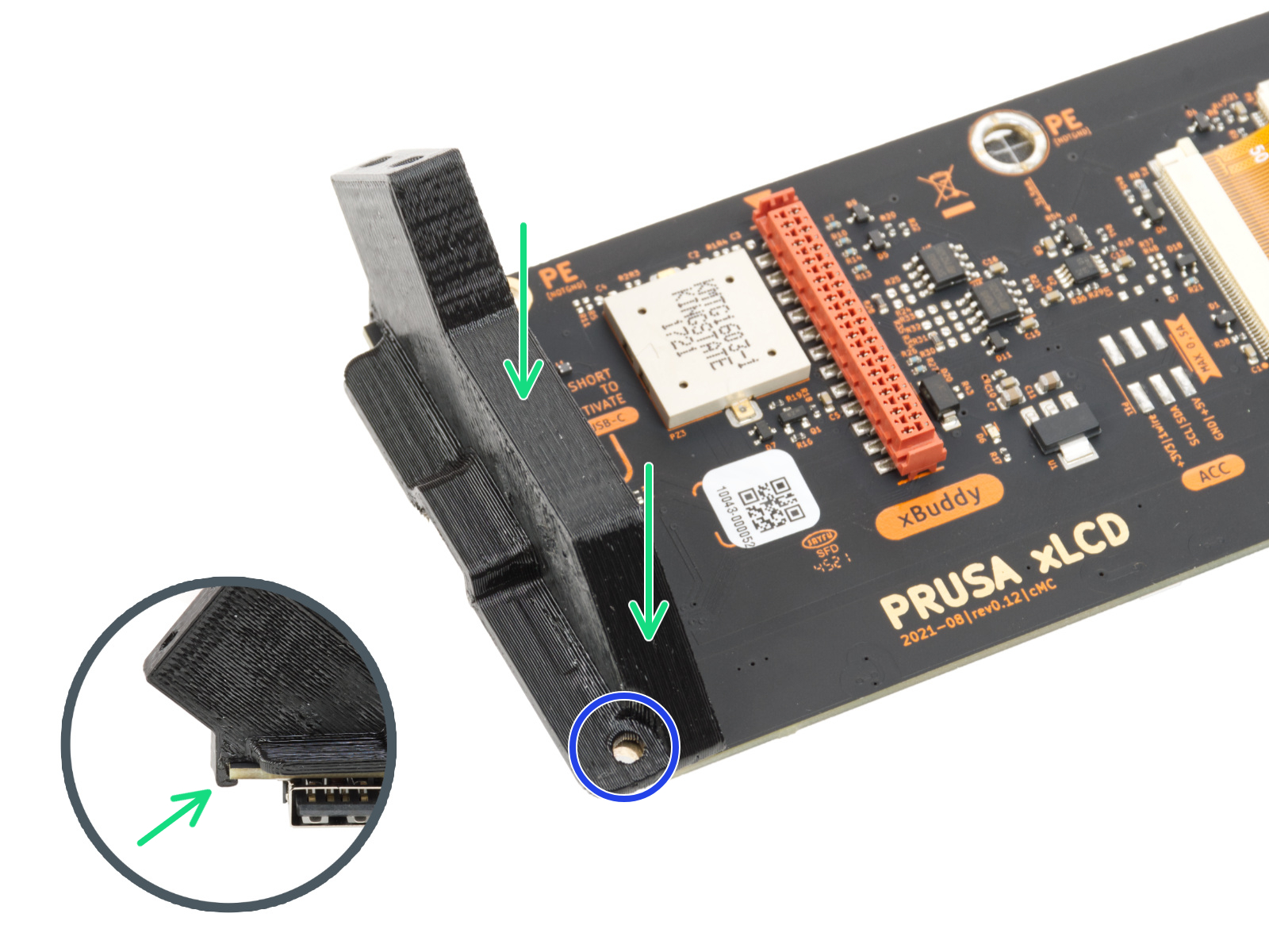


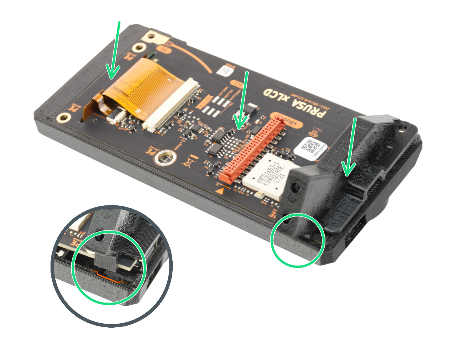

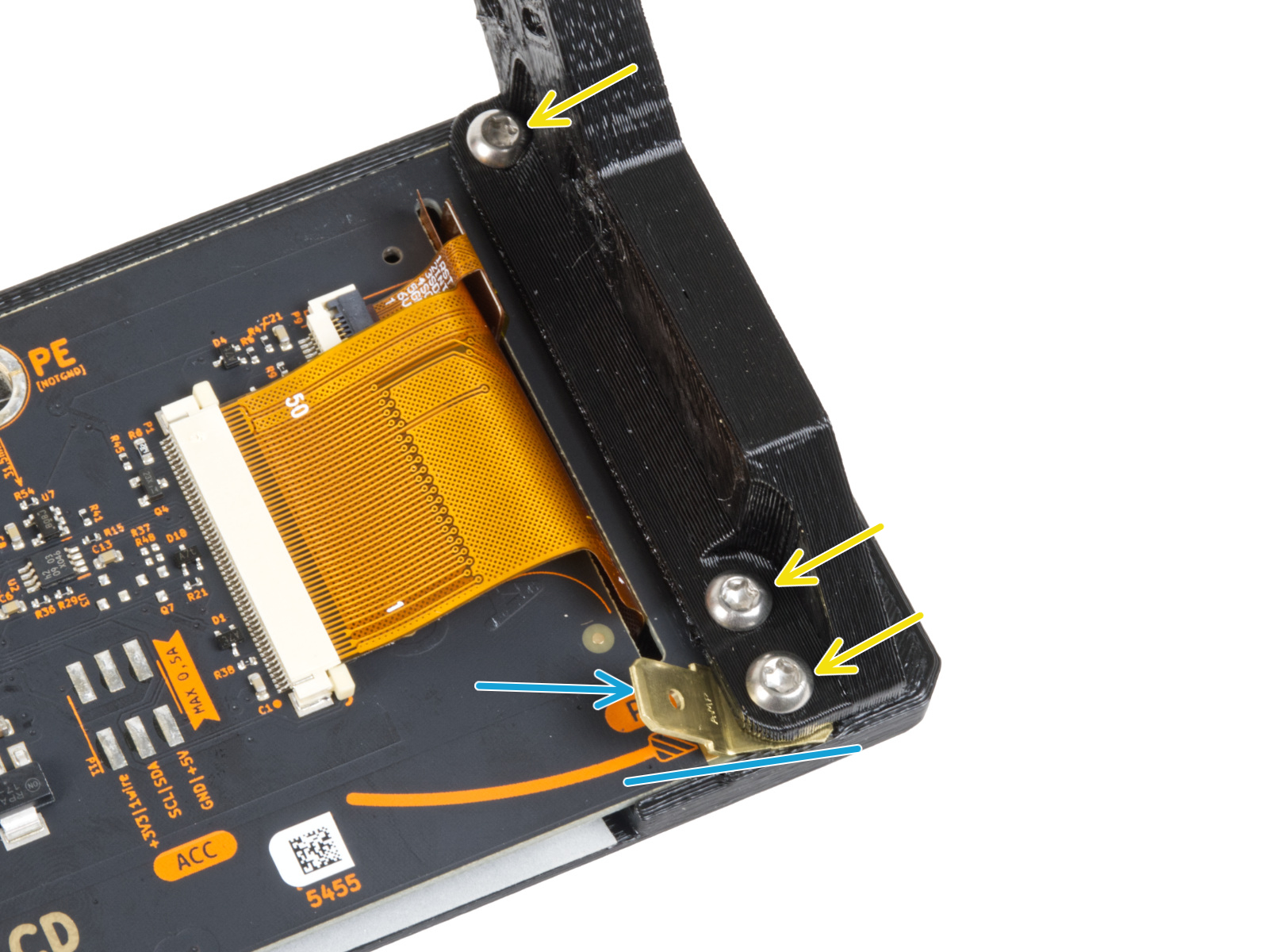


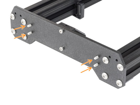
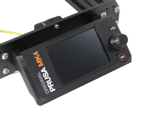


xLCDアセンブリをフロントプレートに取り付けます。ネジはxLCDアセンブリの対応する開口部に合うようにします。


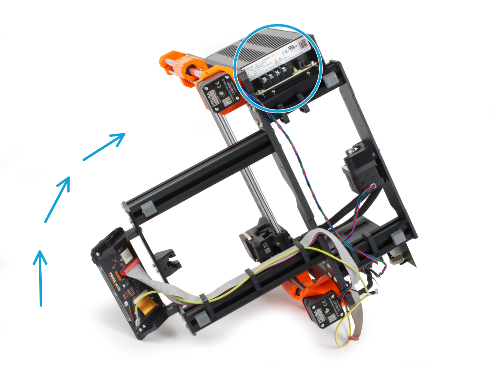
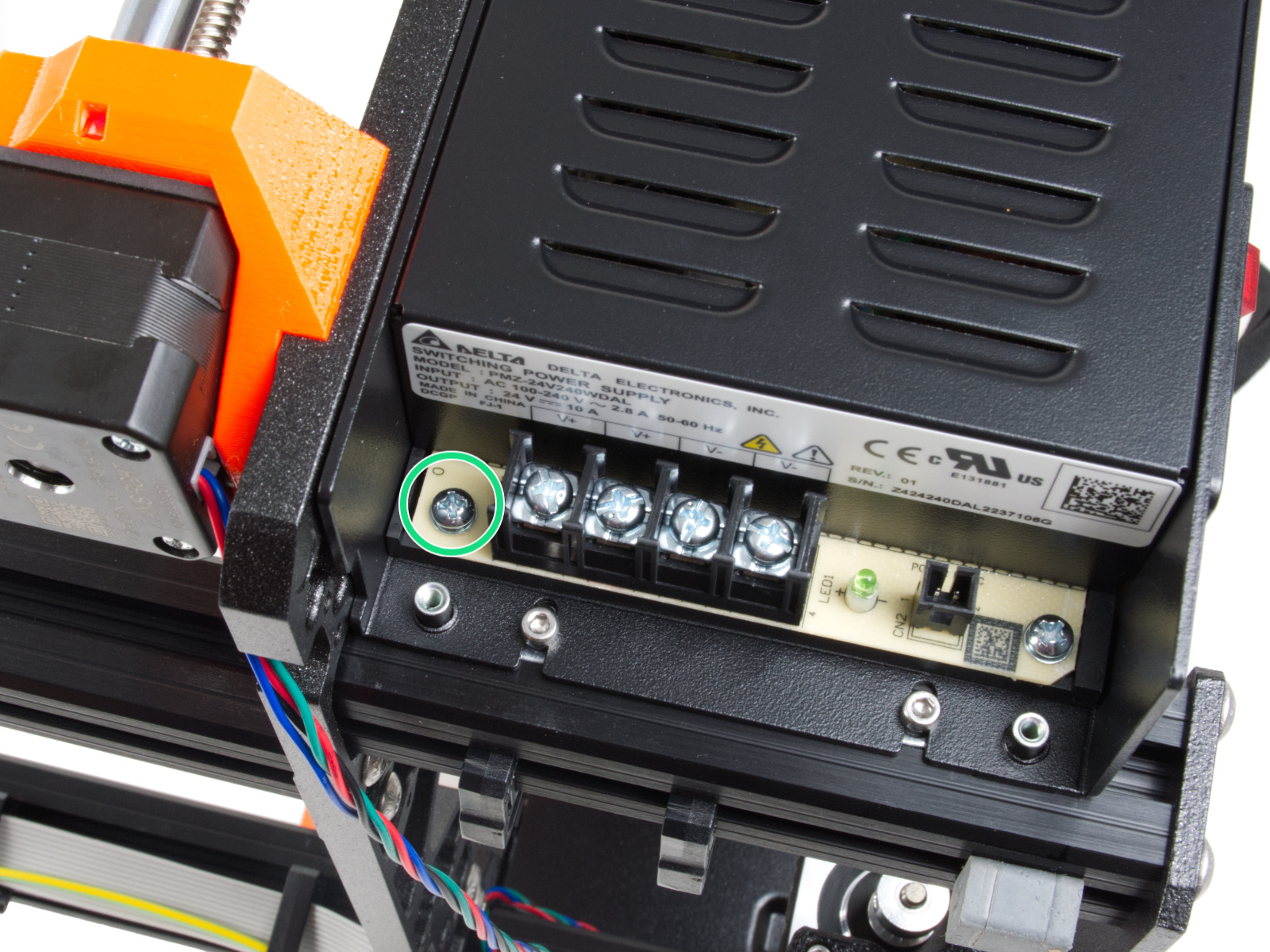
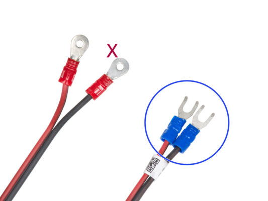
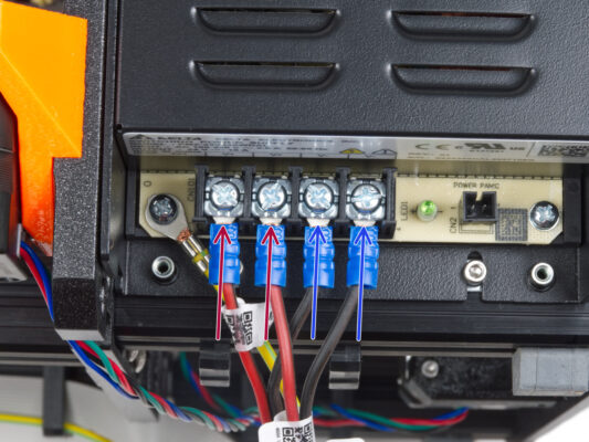
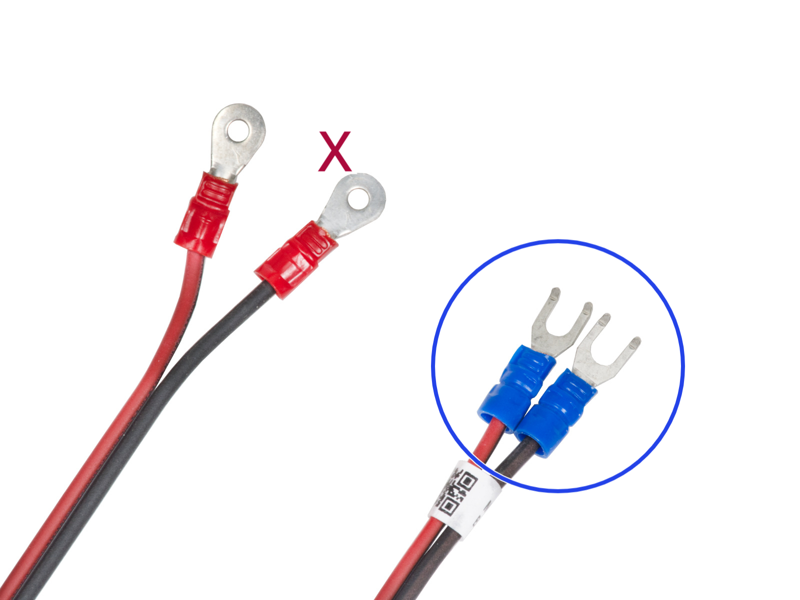


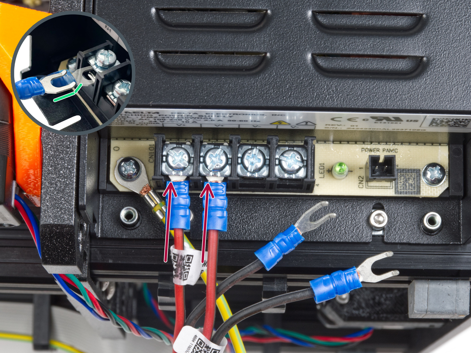
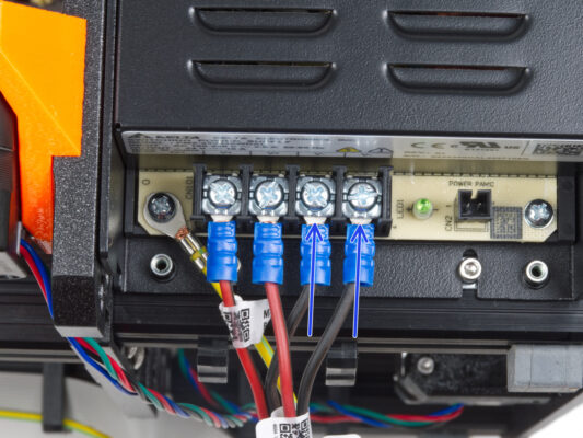

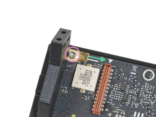
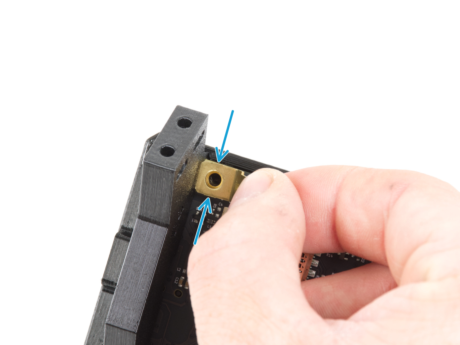
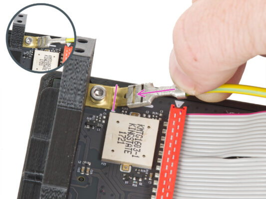
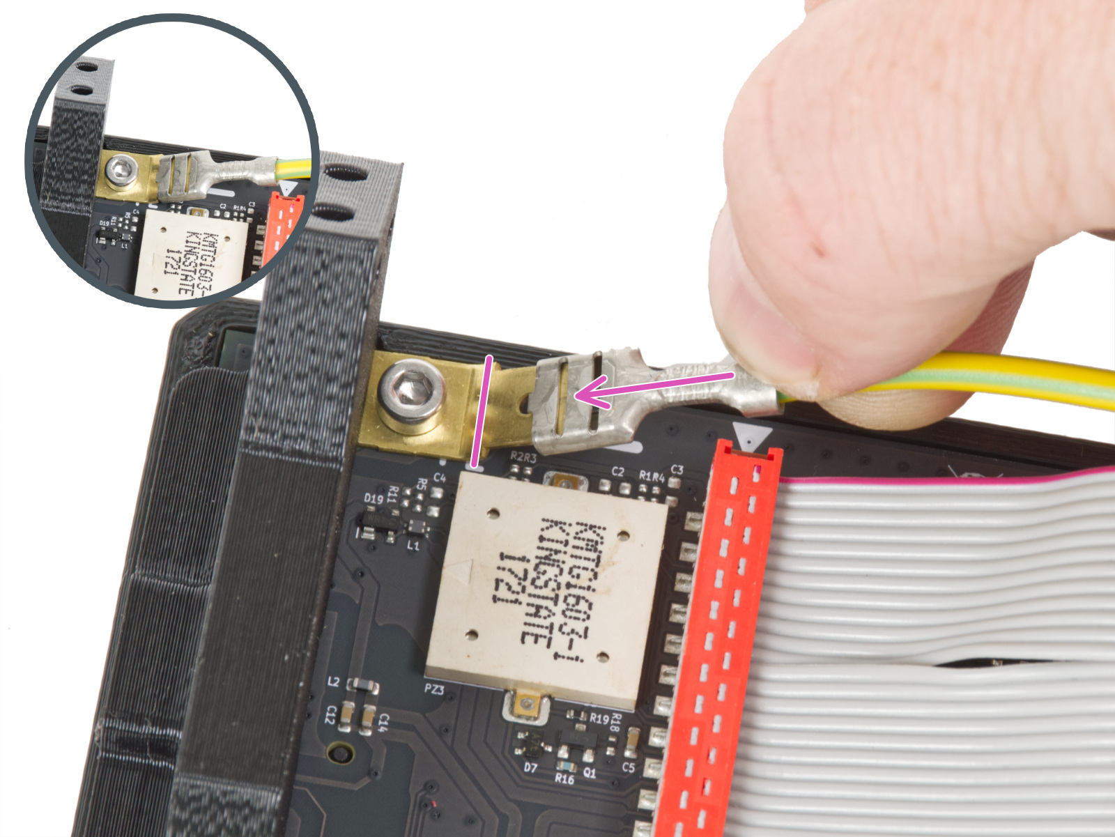
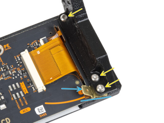
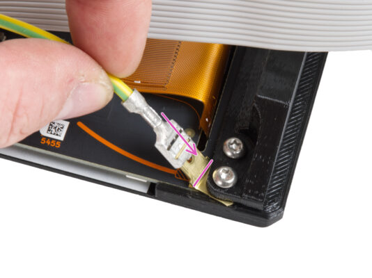
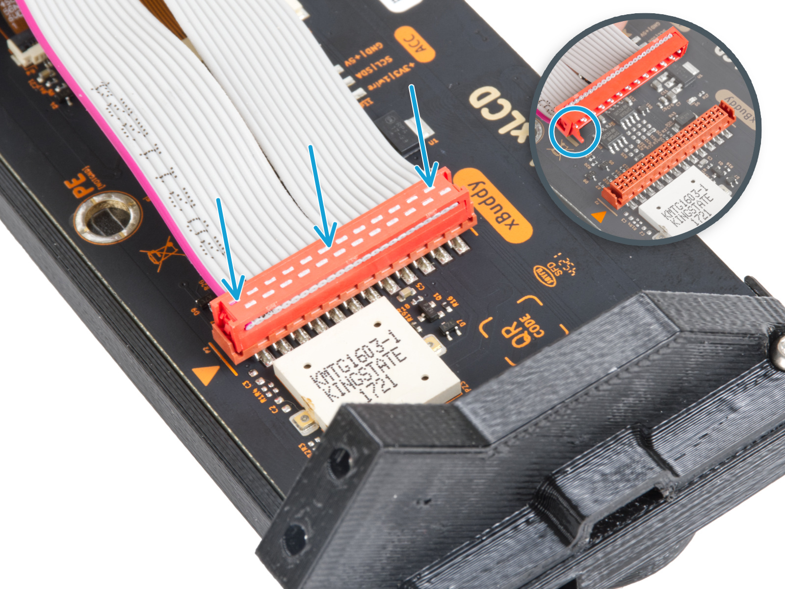
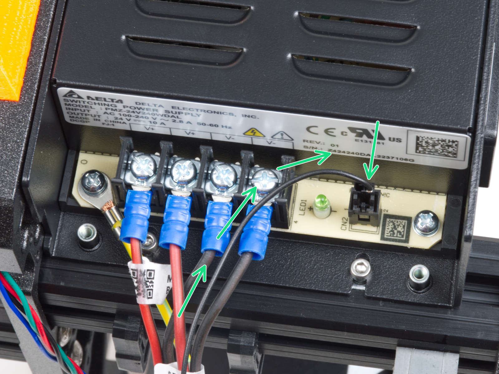
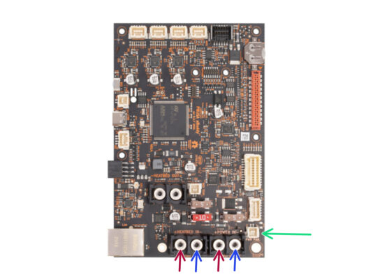
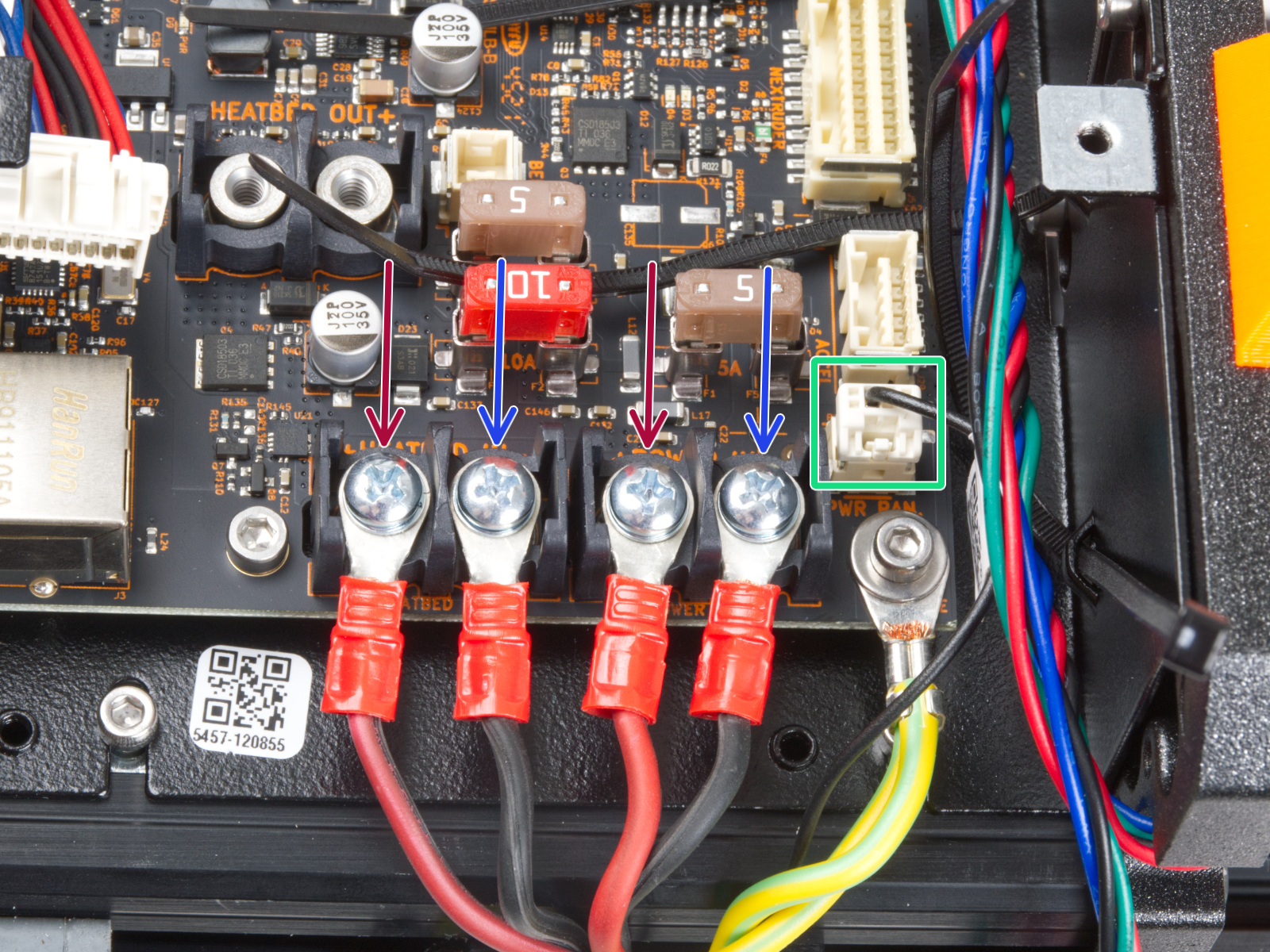
赤(+)線は左の2つの端子に接続されます。
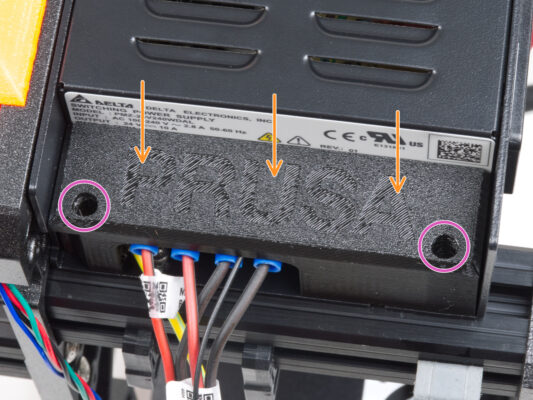
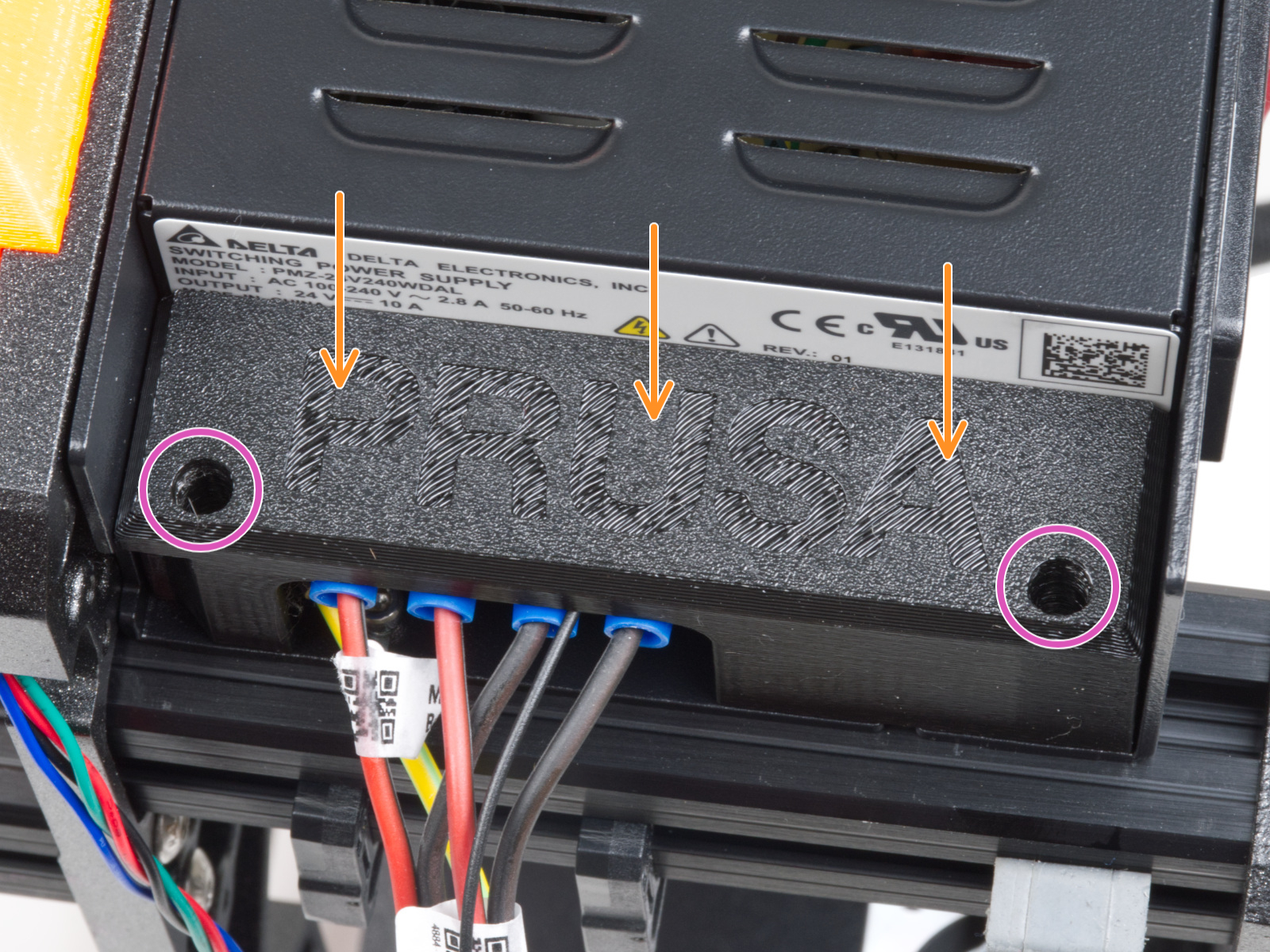
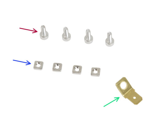
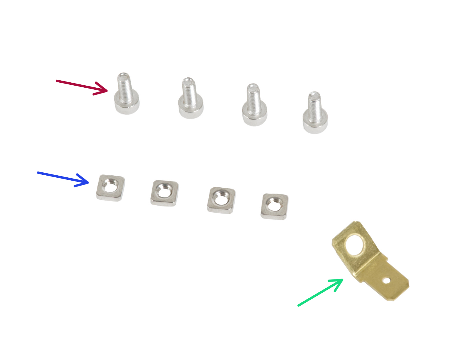
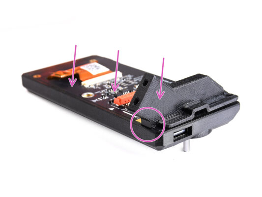
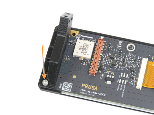
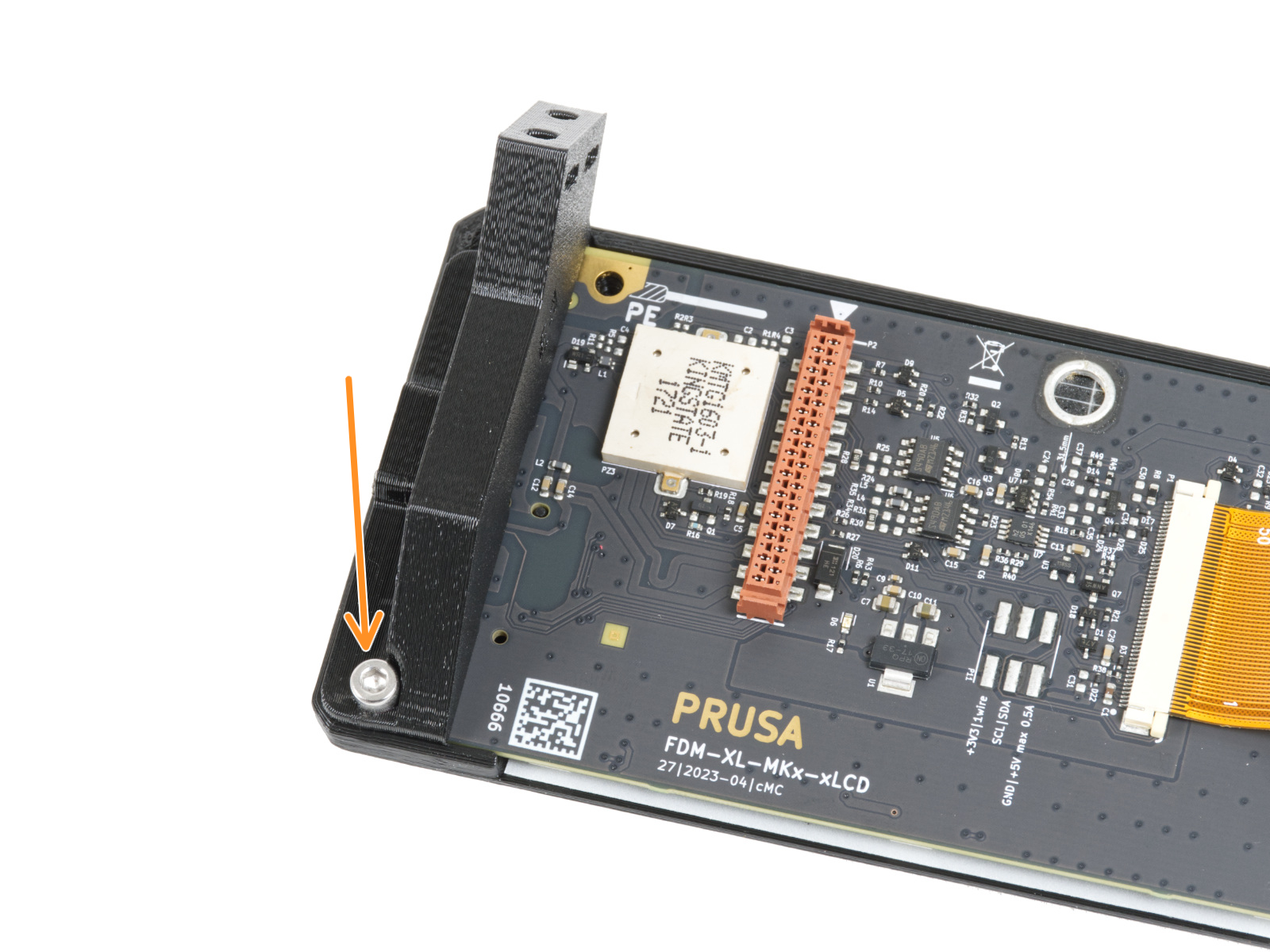
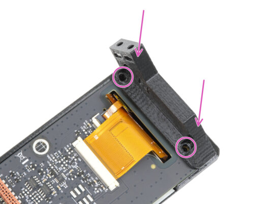
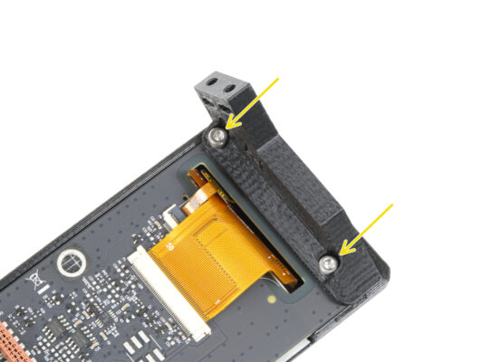
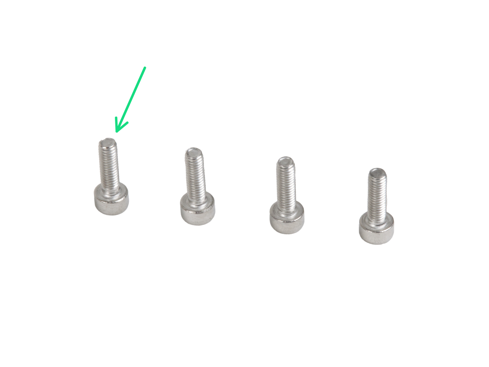
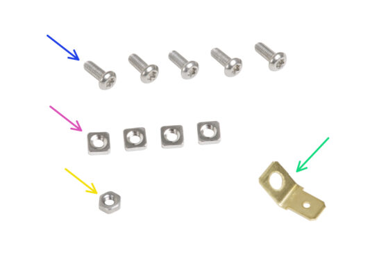
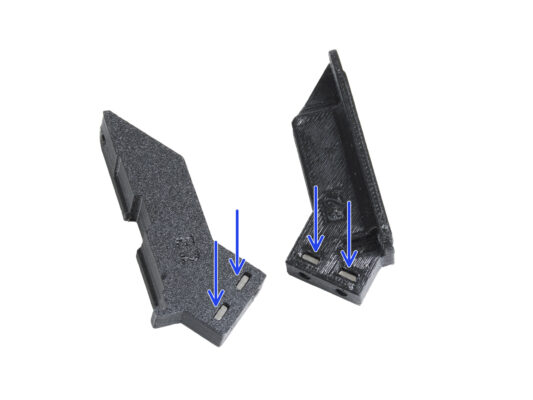
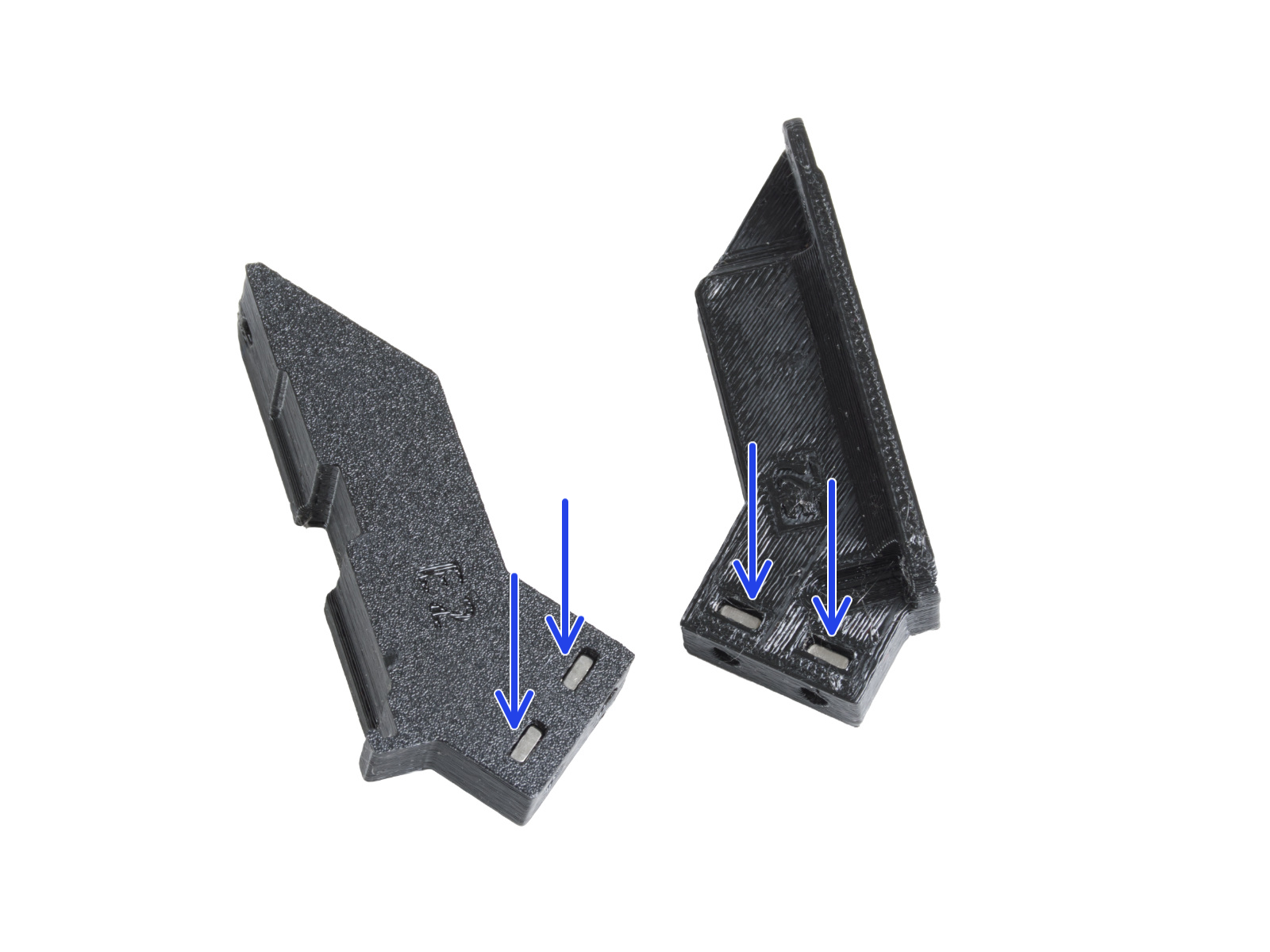
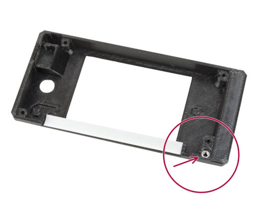
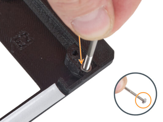
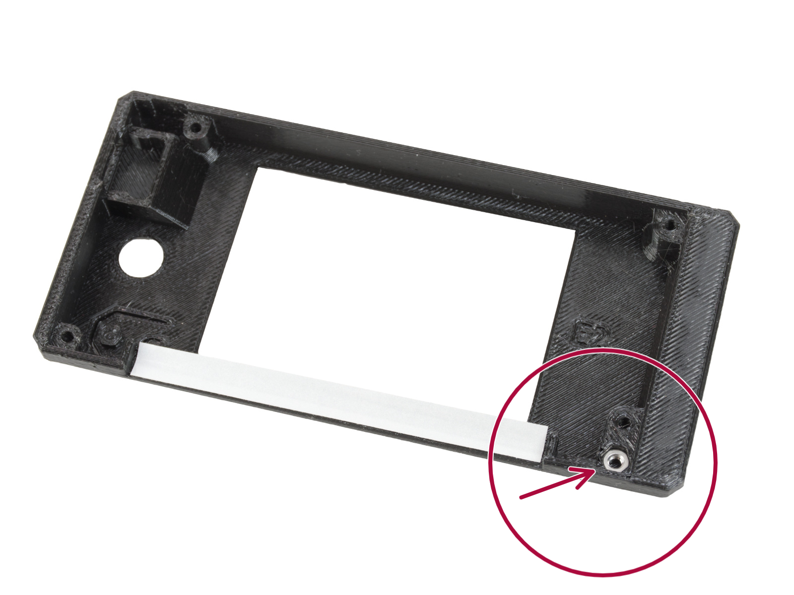
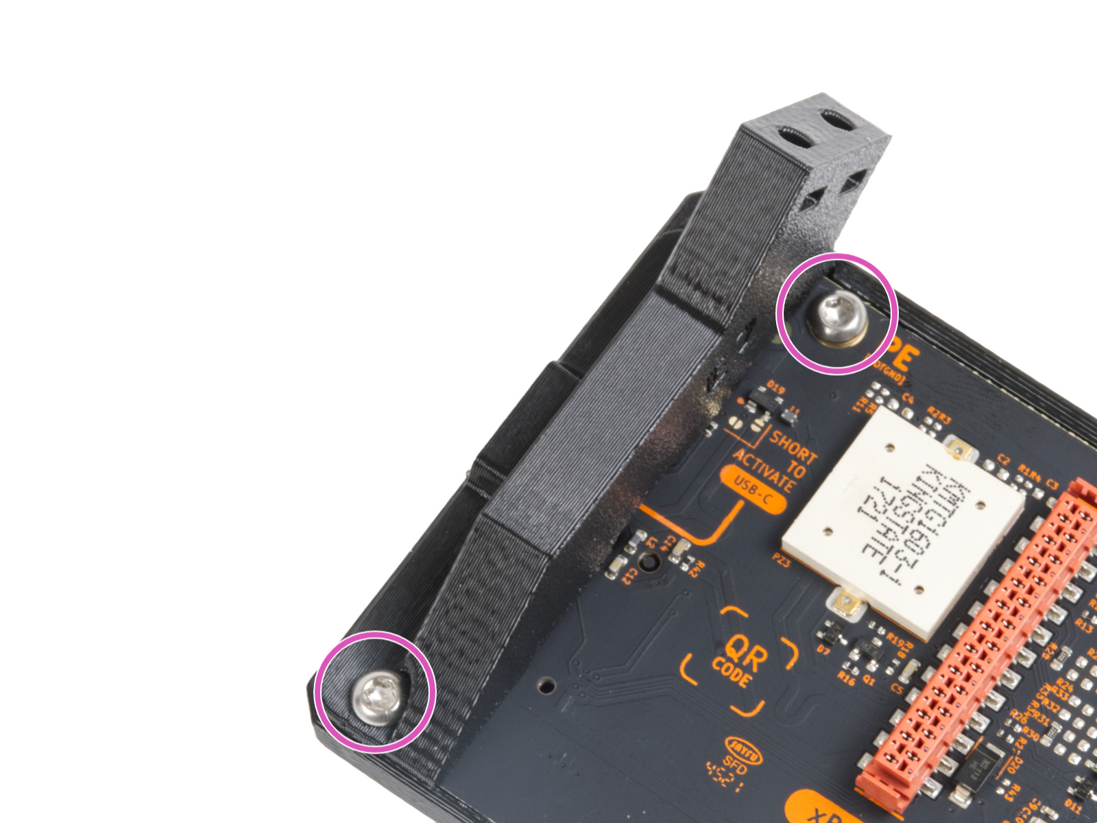
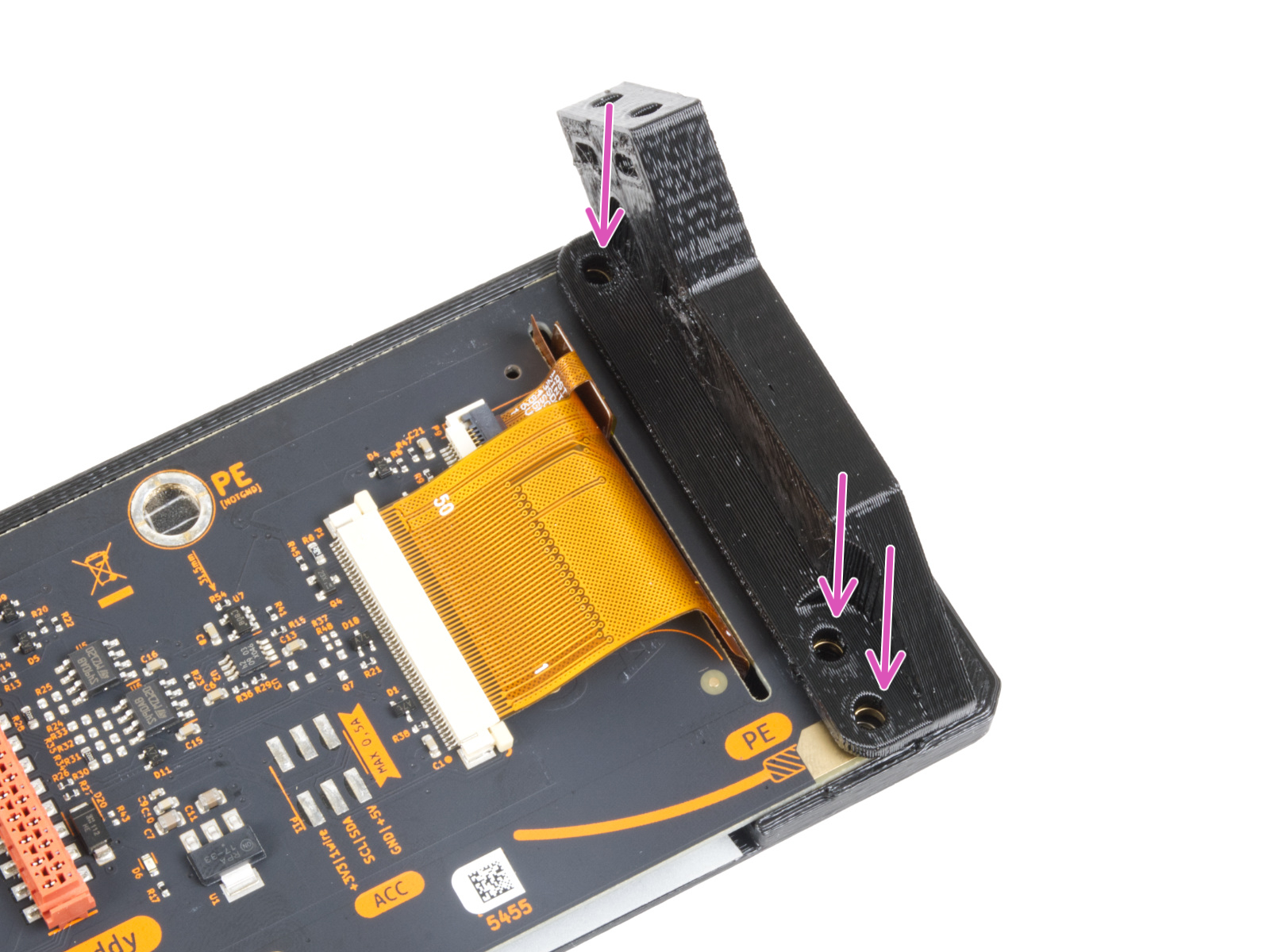
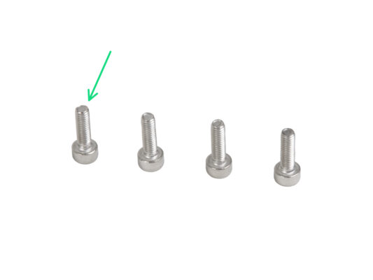
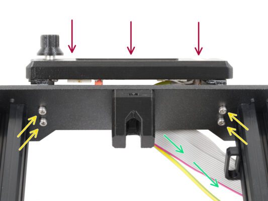
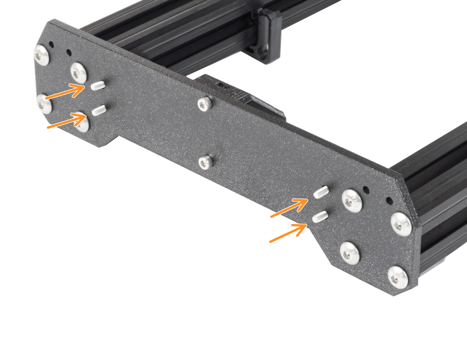
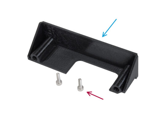
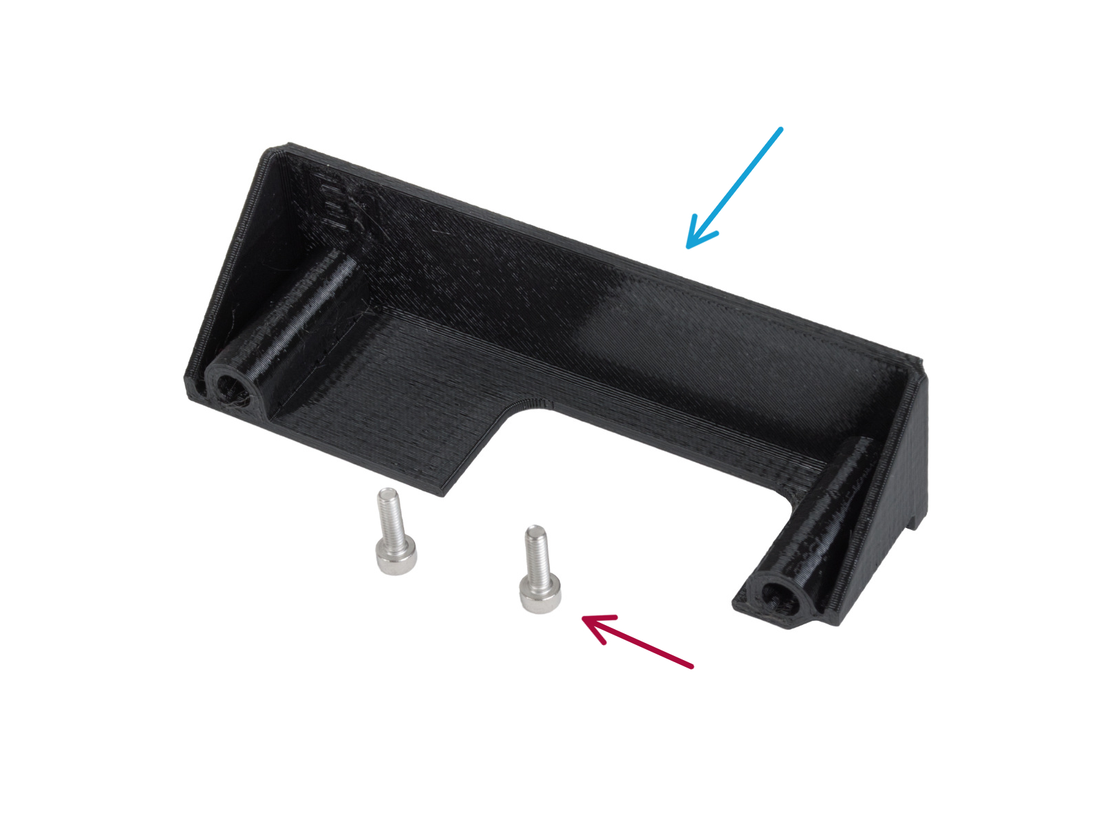
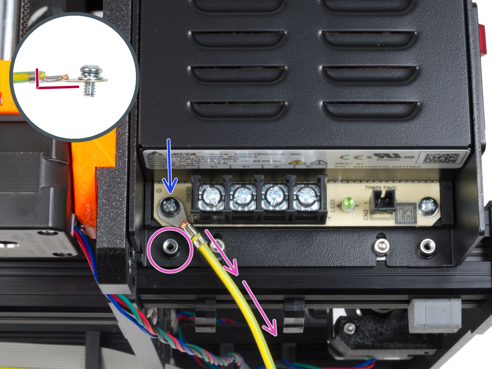
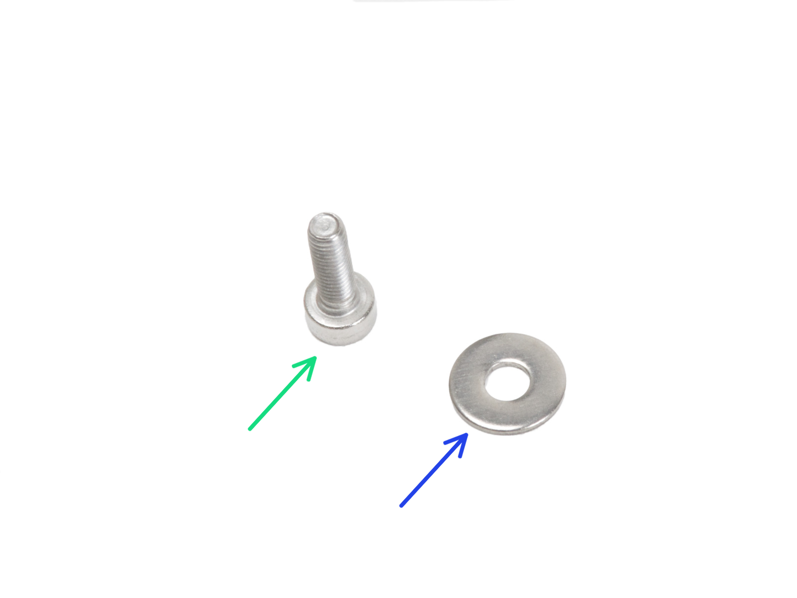
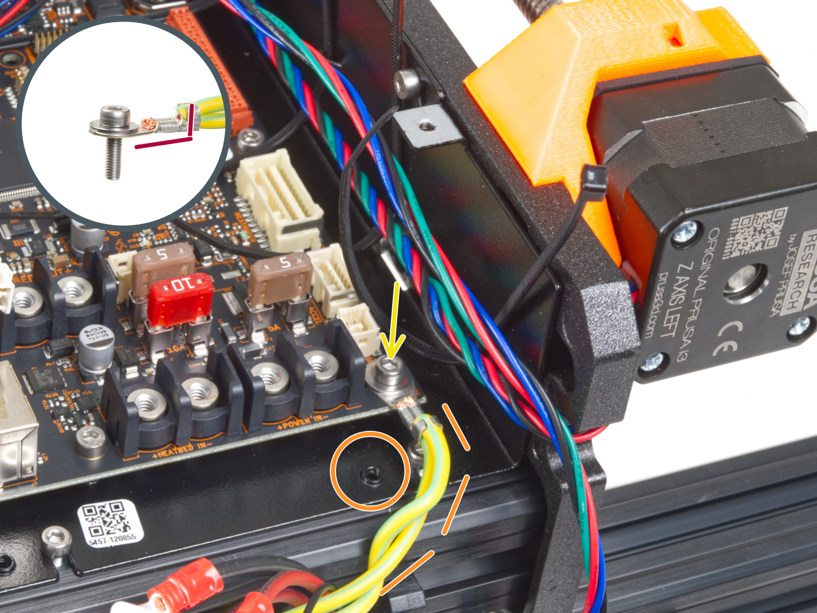
マークした開口部に2本のM3x10ネジを通し、カバーを取り付けます。開口部はかなり深いので注意してください。

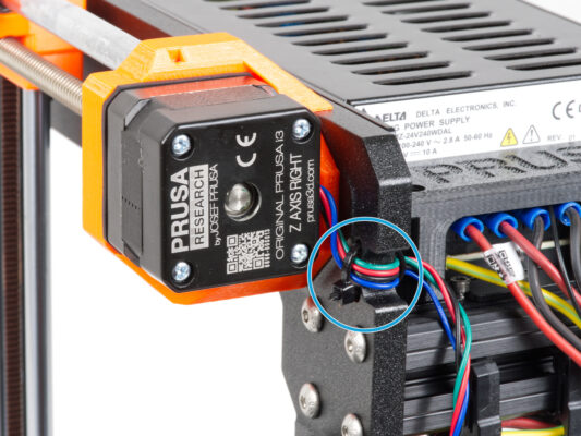
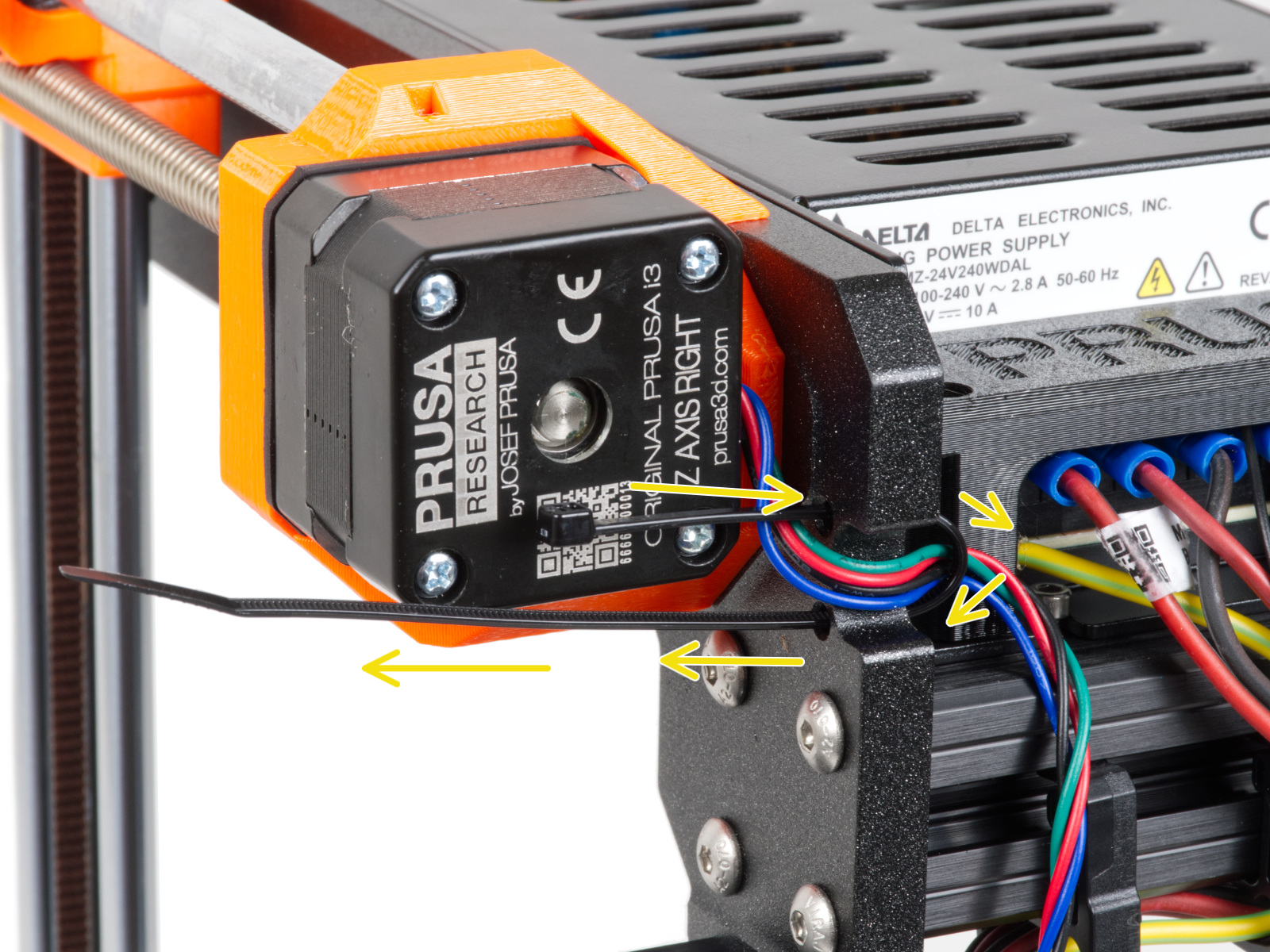
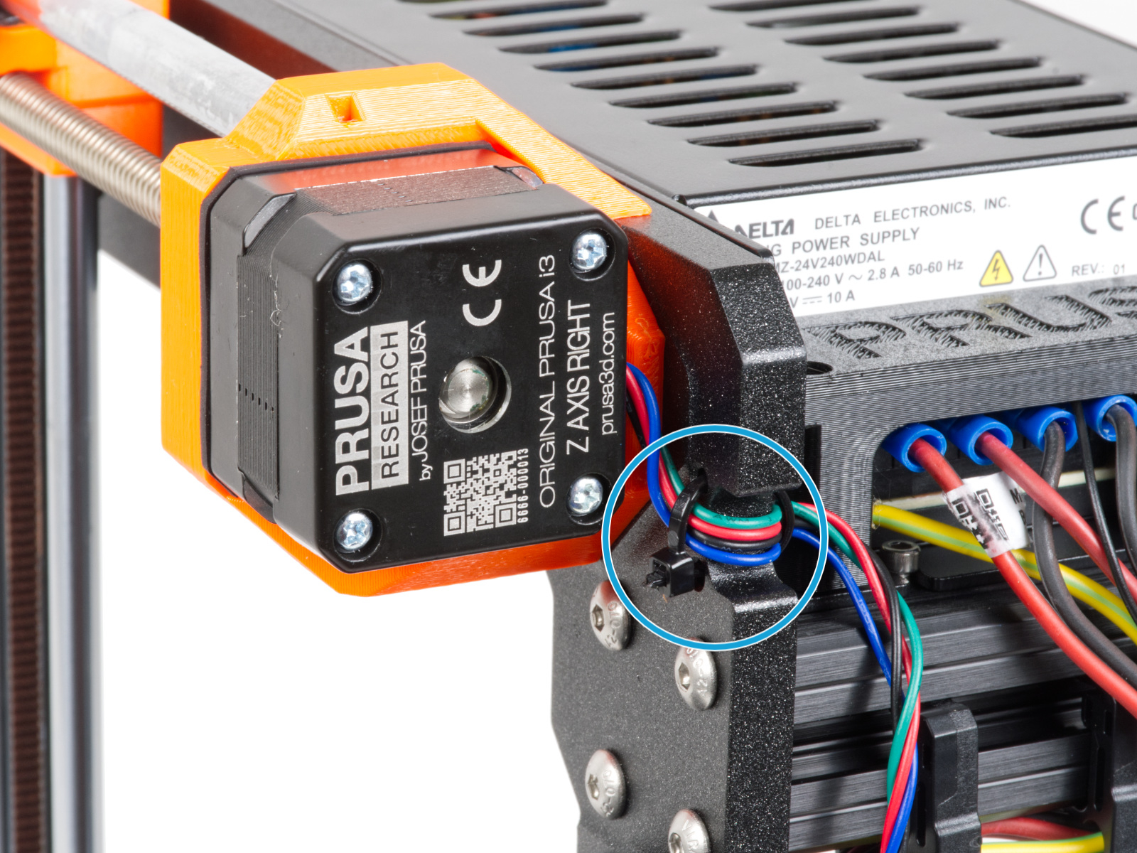
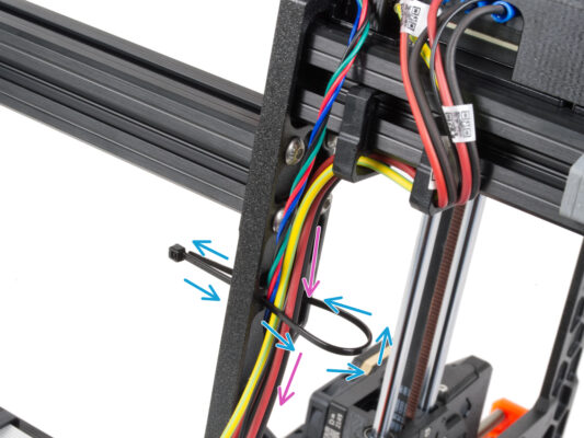
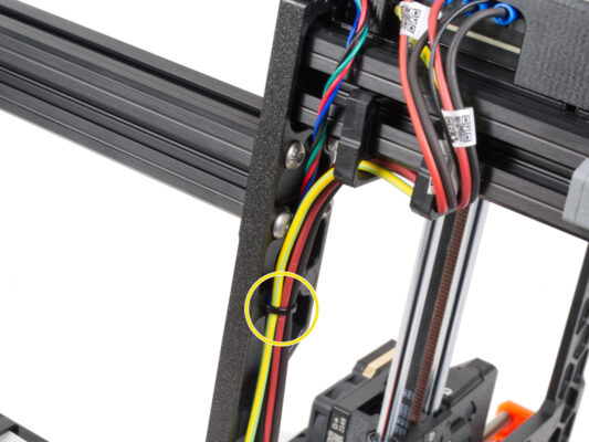
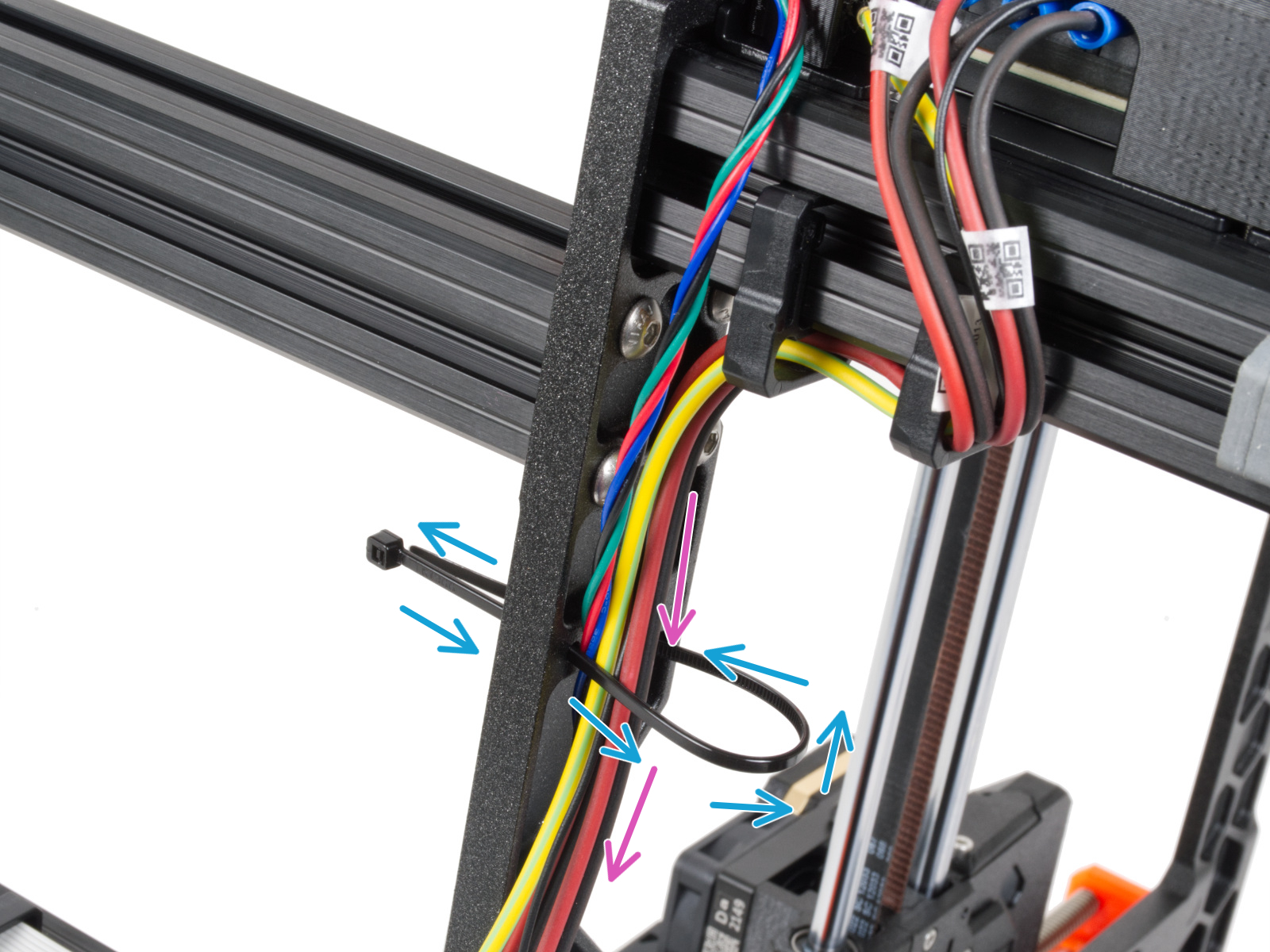

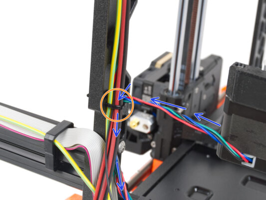
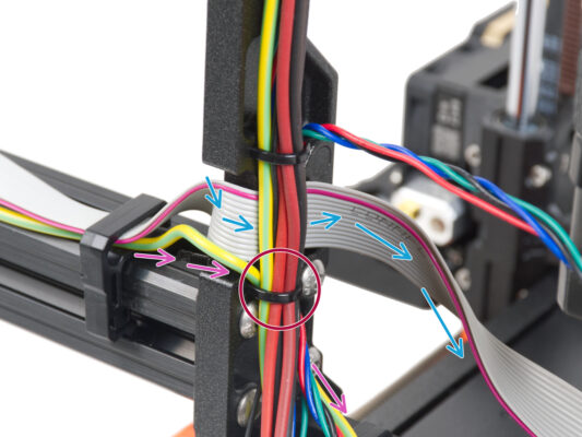
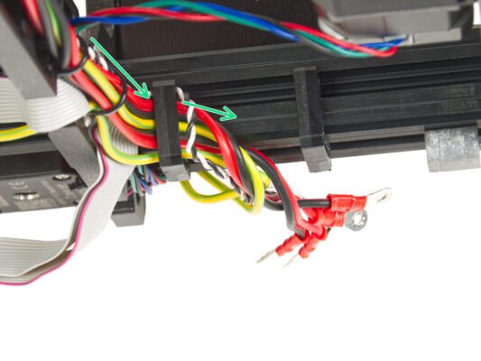
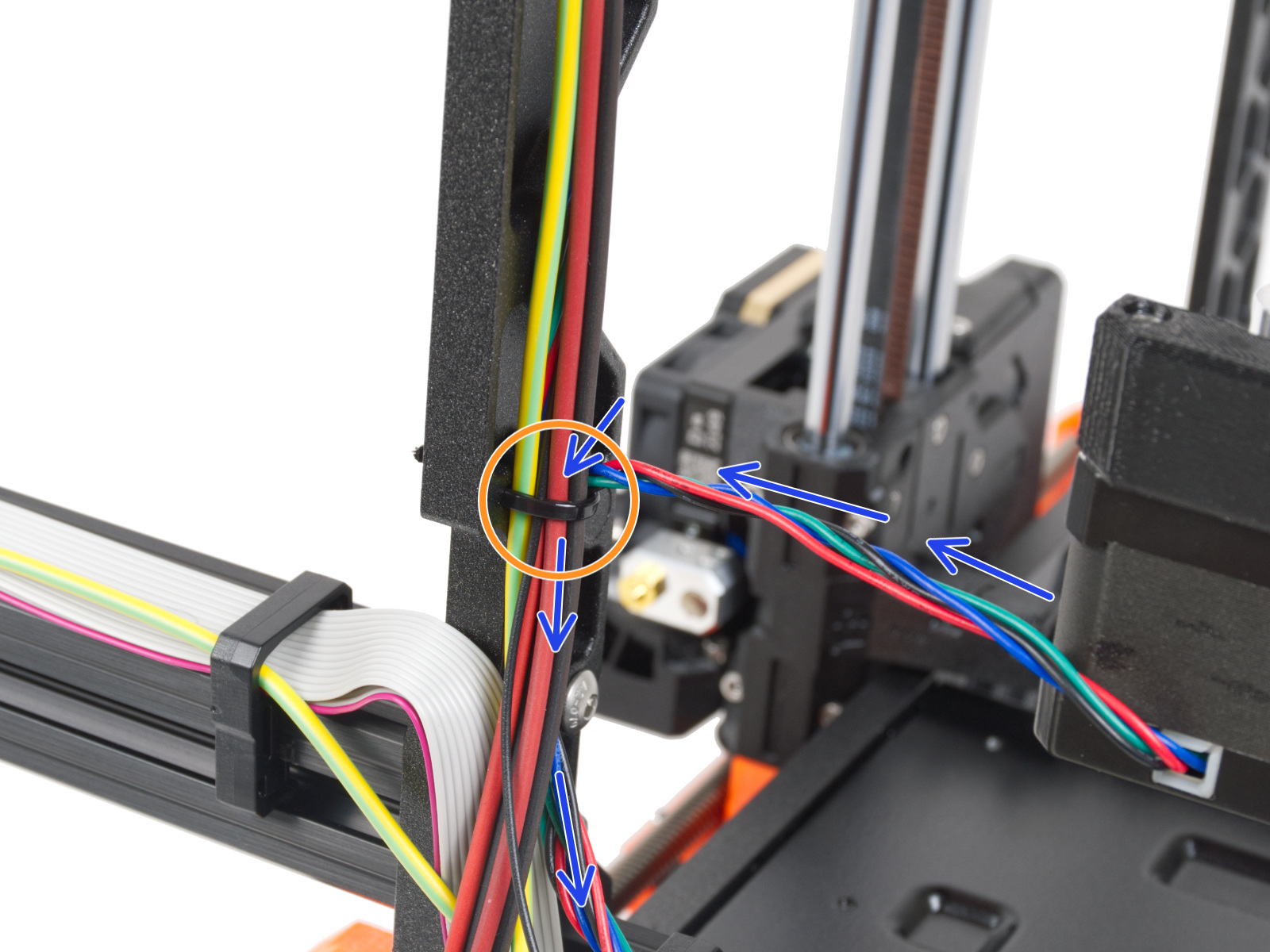
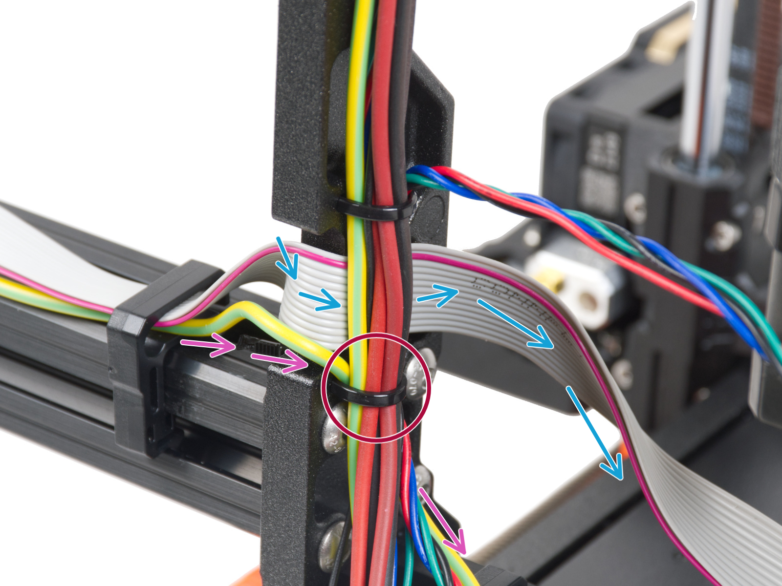

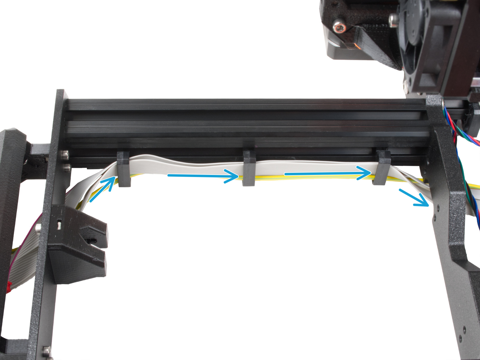
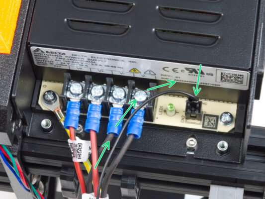
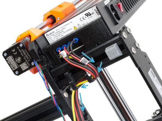
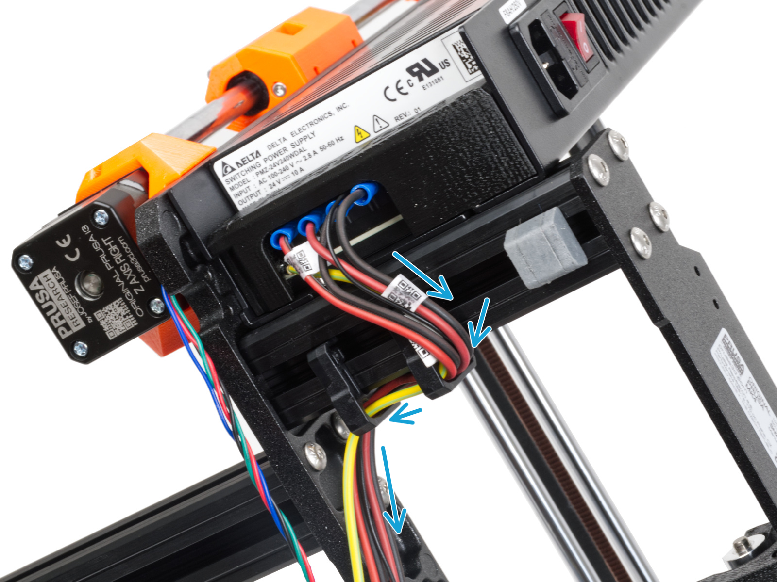
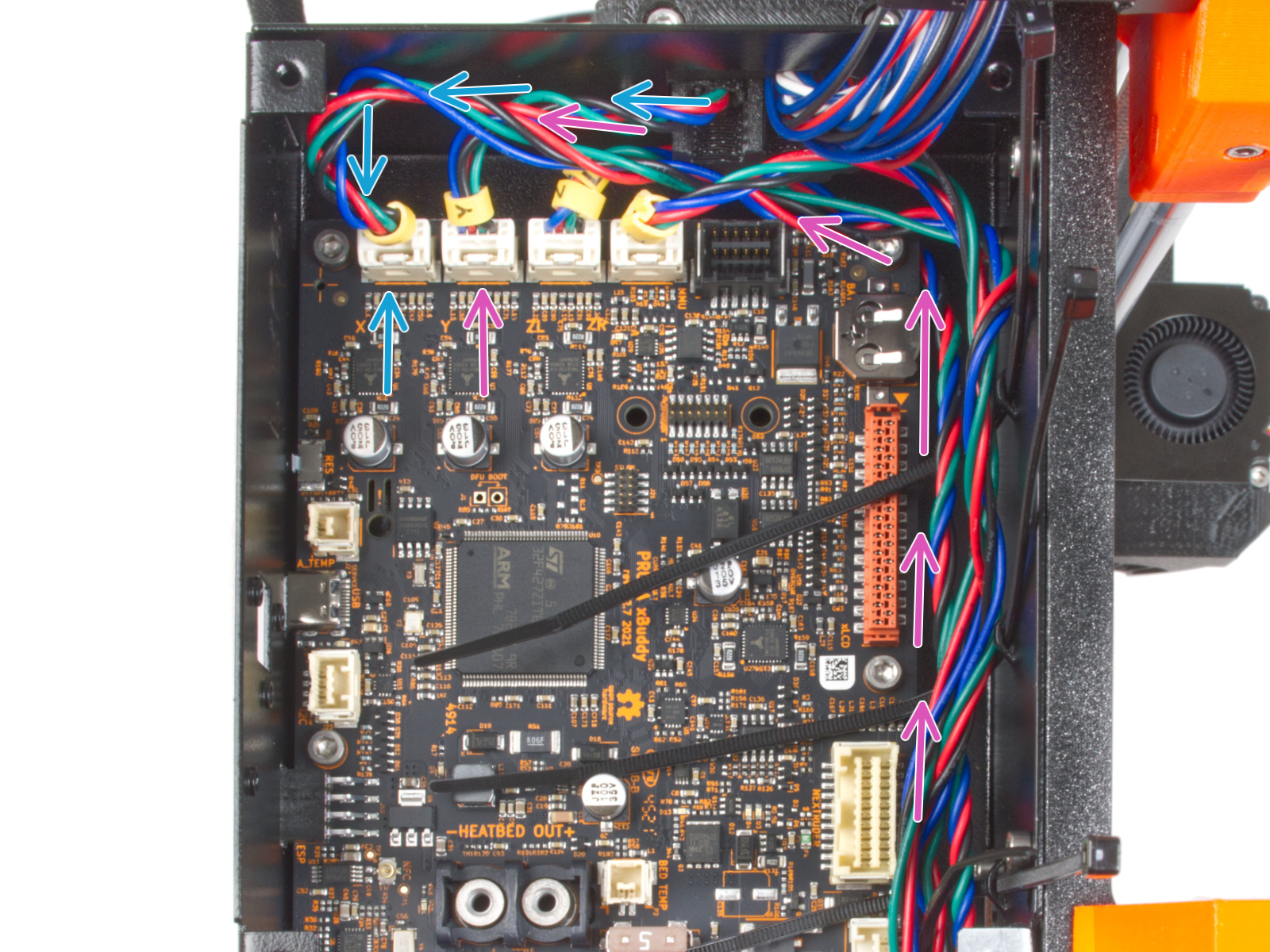
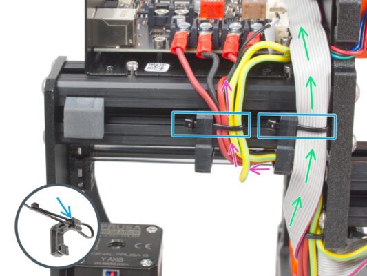
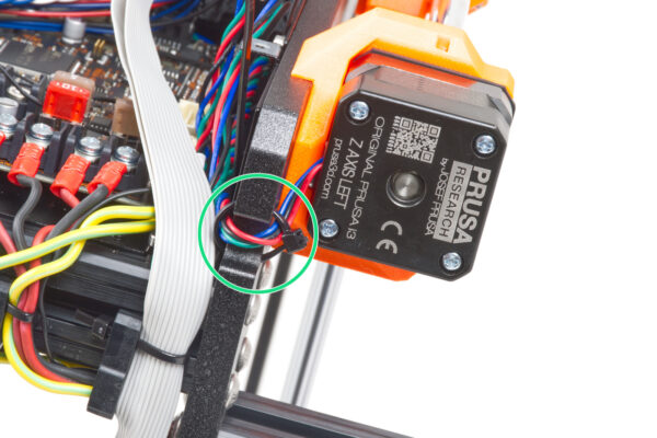
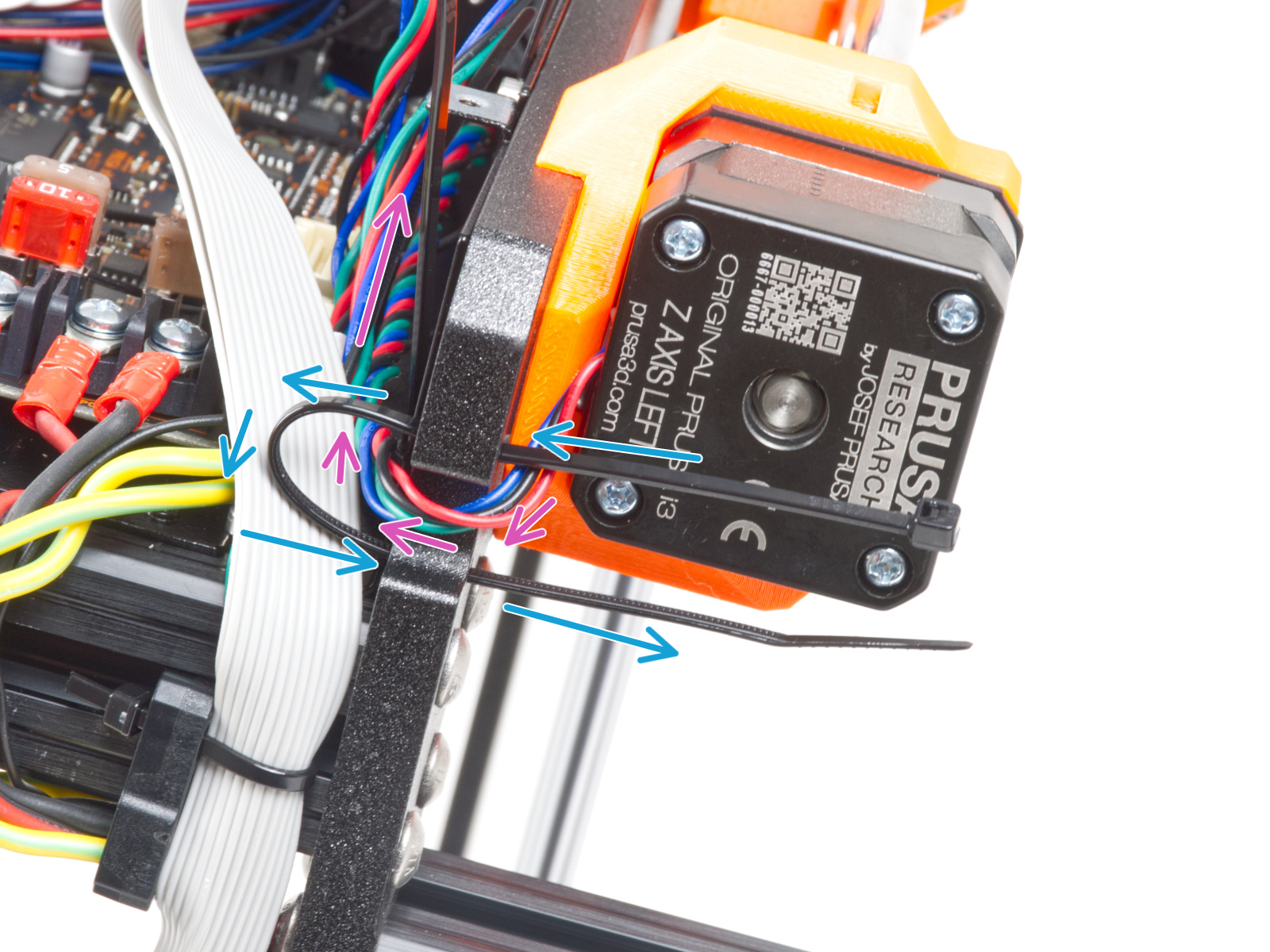
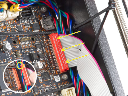
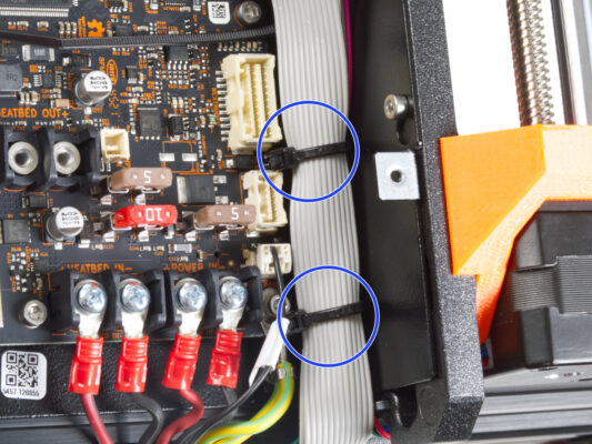
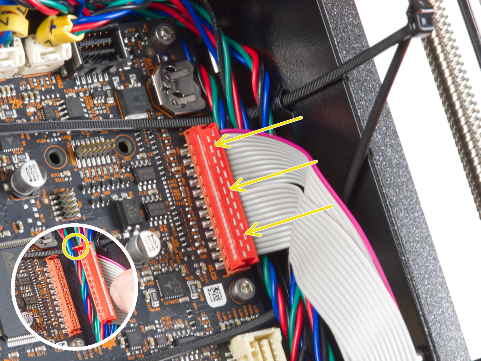
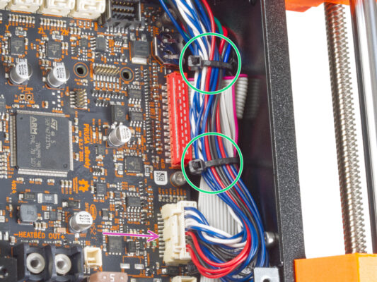
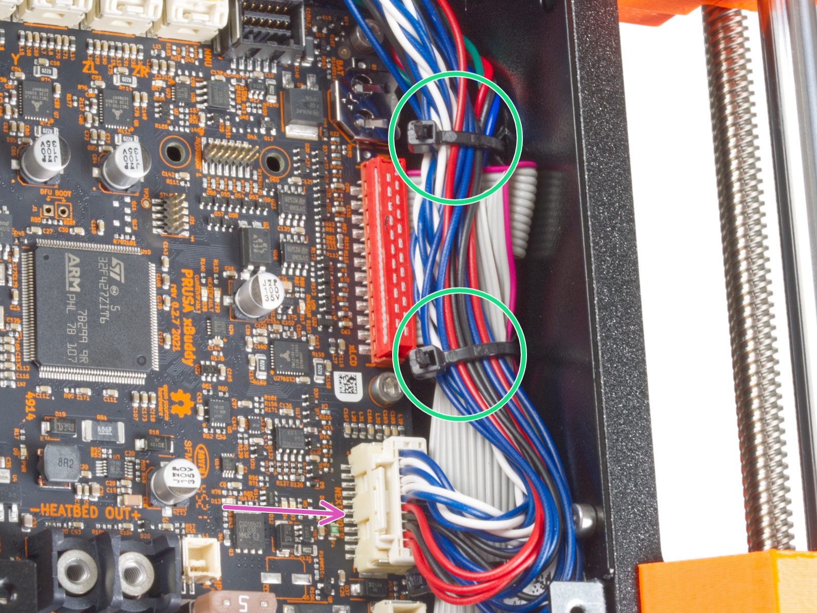
ケーブルを xBuddyボードの方向に導きます。Yモーター右ケーブルを束に含めます。


If you have a question about something that isn't covered here, check out our additional resources.
And if that doesn't do the trick, you can send an inquiry to [email protected] or through the button below.

