JA
  • English
  • Čeština
  • Italiano
  • Deutsch
  • Polski
  • Français
Login

How to replace a PSU (XL)

Menu

How to replace a PSU (XL)

How to replace a PSU (XL)
Relevant for:
Last updated a year ago
How to replace a PSU (XL)
 Difficulty
Moderate
 Steps
24
 Available languages
ENCSPLDEITFR
Introduction
Introduction
This guide will take you through the replacement of one of the Power Supply Units (PSU) on your Original Prusa XL.
The following instructions are compatible with all Original Prusa XL versions.
Necessary tools
Necessary tools
For the following steps, please prepare:
TX10 Torx screwdriver
2.5mm Allen key
3.0mm Allen key
Philips screwdriver
Printer preparation
Printer preparation
Printer preparation
From the rear side, turn the power switch OFF (symbol "O").
Unplug the power cable.
Do not manipulate the PDU and its bolts under any circumstances!
Leave the printer off and disconnected from the mains for at least 10 minutes before proceeding to the next step.
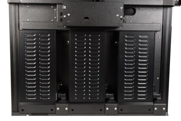
Removing the middle-rear-panel
Using a TX 10 screwdriver, loosen 4x M3x5rT screws. Do not throw them away, we'll use them later.
Remove the middle-rear-panel, gently pull it out.
Disassembling the switch cover
Locate the switch cover on the right side of the PSU that will be replaced.
Using the 2.5mm Allen key, remove the M3x8 screw, and take out the switch cover.
Do not throw the screw away! We'll use it later.
Removing the PSU cover
Using a 2.5mm Allen key, loosen two M3x10 screws that hold the PSU cover. Do not throw them away, we'll use them later.
Carefully slide out the cover. You can use the 2.5mm Allen key or the T10 screwdriver as a lever.
Removing PSU cables (left)
Follow this step in case the PSU to replace is the leftmost one.
Disconnect the following cables:
Two pairs of power cables. Use the Philips screwdriver to loosen them.
Do not throw away the screws and washers, we'll use them later.
PE cable. Use the Philips screwdriver to loosen it.
Leave the screw and washer attached to the PE cable connector.
Power panic
The power panic connector has a safety latch. It is necessary to press the latch before disconnecting. Otherwise, the connector may get damaged.
Removing PSU cables (middle)
Follow this step if the PSU to replace is the central one.
Using the Philips screwdriver, loosen the pair of power cables at the center.
Do not throw away the screws and washers, we'll use them later.
Removing PSU cables (right)
Follow this step if the PSU to replace is the rightmost one.
Using the Philips screwdriver, loosen the pair of power cables at the center.
Do not throw away the screws and washers, we'll use them later.
Removing PSU from frame
Using a 2.5mm Allen key, loosen the M3x16 from the PSU-upper-cover-mount. Start holding the PSU while doing this, with the other hand.
Using a 2.5mm Allen key, loosen slightly, without removing them, the M3x8 screws on the 'bottom mount' of PSU.
With one hand slide the down-angled-ac-adapter upwards, and with the other hand slide up the PSU.
Remove the PSU together with the down-angled-ac-adapter from the frame, then detach the down-angled-ac-adapter.
Do not throw the adapter away, we'll use it later.
Replacing the PSU - parts preparation
For the following steps, please prepare:
PSU (1x)
M3x6 screws (2x)
M3x20rT screw (1x)
M4x12 screw (1x)
PSU-upper-cover-mount (1x)
Down-angled-ac-adapter (1x)
Preparing the PSU
Preparing the PSU
Preparing the PSU
Using a Phillips screwdriver, release the terminal screws, without removing them.
Release the center two terminal screws if you are replacing the central or the right PSU.
Release all of the four terminal screws if you are replacing the left PSU.
From the side of the PSU, insert the Down-angled-ac-adapter.
Turn the PSU power switch ON (symbol "I").
Assembling the PSU upper-cover-mount
Insert an M4x12 screw into the PSU-upper-cover-mount.
Locate the hole on the top left side of the PSU.
Attach the PSU-upper-mount-cover to the PSU and secure the M4x12 screw using a 3mm Allen key.
Securing the PSU to the frame
On the left side of the PSU, insert the M3x20rT screw into the PSU-upper-cover-mount and secure the cover with the back plate of the printer.
On the bottom of the PSU, tighten two M3x6 screws using a 2.5mm Allen key.
Pushing down the Down-angled-ac-adapter, secure its position.
Connecting the left PSU cables (CRITICAL) - part 1
WARNING: Triple-check you have connected the cables correctly. There is a risk of damaging the PSU or the printer itself, if the cables are connected incorrectly or not tightened properly!
Starting from the left, the PSU polarity is: ++--
Make sure the bent part of the cable connector is always facing up, and connected under the square washer.
One cable pair is labeled with B.
Connect the red cable on the leftmost connector.
Connect the black cable on the rightmost connector.
The other cable pair does not have a label.
Connect the red cable on the center-left connector.
Connect the black cable on the center-right connector.
We will connect the remaining cables on the next step.
Connecting the left PSU cables (CRITICAL) - part 2
WARNING: Triple-check you have connected the cables correctly. There is a risk of damaging the PSU or the printer itself, if the cables are connected incorrectly or not tightened properly!
Starting from the left, the PSU polarity is: ++--
Plug the power panic cable on its connector.
Using the Philips screwdriver, fully tighten the bolt with the washer under it to connect the PE cable.
Double-check now the correctness of the connection for the two pairs of power cables.
Triple-check again that all screw-attached connectors are correctly connected, as tight as possible, and with the correct polarity.
Connecting the center PSU cables (CRITICAL)
WARNING: Triple-check you have connected the cables correctly. There is a risk of damaging the PSU or the printer itself, if the cables are connected incorrectly or not tightened properly!
Starting from the left, the PSU polarity is: ++--
Make sure the bent part of the cable connector is always facing up, and connected under the square washer.
The cable pair does not have a label.
Connect the red cable on the center-left connector.
Connect the black cable on the center-right connector.
Triple-check again that all screw-attached connectors are correctly connected, as tight as possible, and with the correct polarity.
Connecting the right PSU cables (CRITICAL)
WARNING: Triple-check you have connected the cables correctly. There is a risk of damaging the PSU or the printer itself, if the cables are connected incorrectly or not tightened properly!
Starting from the left, the PSU polarity is: ++--
Make sure the bent part of the cable connector is always facing up, and connected under the square washer.
The cable pair is labelel A.
Connect the red cable on the center-left connector.
Connect the black cable on the center-right connector.
Triple-check again that all screw-attached connectors are correctly connected, as tight as possible, and with the correct polarity.
Assembling the switch cover
Insert the M3x8 screw into the switch-cover.
On the right side of the PSU, locate the hole in the back plate of the printer.
Using a 2.5mm Allen key, secure the cover screw with the back of the printer.
Assembling the PSU cover
Insert both M3x10 screws into the PSU cover.
Insert the prepared PSU cover under the PSU.
Tighten both M3x10 screws using a 2.5mm Allen key.
Testing the printer
Testing the printer
From the rear side, plug in the power cable.
Turn the power switch ON (symbol "I").
Perform a selftest or test the printer heating as a test for the replaced PSU.
Good job!
Good job!
That's it, good job! You successfully replaced the PSU on your Original Prusa XL.
Was this guide helpful?

Comments

Still have questions?

Still have questions?

If you have a question about something that isn't covered here, check out our additional resources.
And if that doesn't do the trick, you can send an inquiry to [email protected] or through the button below.

Contact us