EN
  • Čeština
  • Español
  • Italiano
  • Deutsch
  • Polski
  • Français
  • 日本語
Login

7. Heatbed & PSU assembly

7. Heatbed & PSU assembly

7. Heatbed & PSU assembly
Relevant for:
Last updated 2 years ago
7. Heatbed & PSU assembly
 Difficulty
Moderate
 Steps
26
 Available languages
CSPLDEJAESITFR
Heatbed cable assembly (part 1)
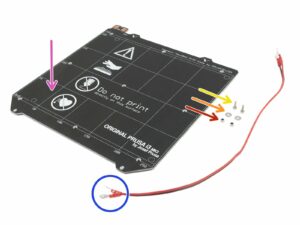
For the following step please prepare:
Heatbed MK52 24V (1x)
Power cable (1x)
M3x10 screw (2x)
M3/3,2/9/0,8 washer (2x)
M3nN nylock nut (2x)
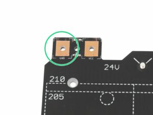
IT IS VERY IMPORTANT to connect the power cable correctly. Before you start the assembly have a look at the pins. The one on the left with "GND" sign must be connected to the BLACK WIRE.
Heatbed cable assembly (part 2)
Place the black wire above the pin with "GND" sign. Make sure you are using the rounded connector.
Place the washer above the rounded cable connector.
Press the M3x10 screw through all parts.
Hold the screw and carefully turn the heatbed upside down.
Place the M3nN Nylock nut on the top of the M3 screw and tighten it slightly.
Turn the heatbed back, using pliers and Allen key tighten the screw. We need to adjust cable position in the next step, therefore do not tighten the screw too firmly.
Repeat this procedure for the second (red) wire.
Heatbed cable assembly (part 3)
Before proceeding further, please check again the cable is connected with the correct polarity to the heatbed and properly tightened. Otherwise, there is a risk of damage to the printer!
BLACK wire must be connected to the "GND"
RED wire must be connected to the "VCC"
The cable cover, which will be applied later requires the connectors to be slightly inclined towards each other. Press them gently, but leave a gap between them.
Design of your heatbed might slightly differ from the last picture.
Now, tighten both screws using the Allen key and the pliers.
Preparing the heatbed
For the following steps, please prepare:
Heatbed MK52 (1x)
Textile sleeve 5 x 300 mm (1x)
M3nN nyloc nut (1x)
M3n nut (2x)
M3x10 screw (3x)
Heatbed-cable-cover-clip (1x)
Heatbed-cable-cover (1x)
Mounting the heatbed-cable-cover
Place the bigger heatbed-cable-cover next to the heatbed. See the hole, which has to match the one on the heatbed.
Now, place the cover on the heatbed and align it.
Use the M3x10 and push it through the cover.
Mounting the heatbed-cable-cover
Hold the screw with your thumb and flip the heatbed upside down.
Use M3nN nyloc nut and tighten the screw.
Use pliers and Allen key to tighten the nut with the screw.
Proper cable management
Do not stretch the black thermistor cable, leave some slack under the heatbed, so when the heatbed moves during print, the cable won't get stretched resulting in disconnection from the center of the heatbed.
You can guide the thermistor cable, through both gaps between the heatbed cover screws.
However, the slack shouldn't be causing the cable to sag down more than few millimetres. Otherwise, the cable might rub against the printer's frame and damage itself! Turn the heatbed upside-down to check this.
Guide the black thermistor cable next to the heatbed heater cable and wrap it few times around (see the photo).
Wrapping the heatbed cables
Use the textile sleeve and wrap the cables from the heatbed. Start by wrapping a few centimeters of the sleeve behind the heatbed cover.
When the first "wrap" is ready, slide it inside the heatbed cover. Ensure it is at least 5-6 mm.
Before you continue with wrapping the sleeve, we need to fix it in the cable cover. Please proceed to the next step.
Securing the sleeve in place
Take the smaller cover you have prepared earlier and place it like in the picture.
Make sure the thermistor cable is in the middle going through a cutout in the printed part!!! Otherwise, you will pinch and possibly break the cable!!!
Hold the cover and flip the heatbed back. Insert two screws M3x10 and tighten them, proceed with caution and tighten both screws equally.
Don't tighten the screw completely on one side and then on the other (see the second picture)!
Your tightened cover should look like the last picture.
Finalizing the wrap
Finalizing the wrap
Now, finish wrapping the cable into the textile sleeve.
When done, slightly twist the sleeve (not the cables inside). The sleeve will evenly wrap all around the cable bundle.
Mounting the heatbed (part 1)
Push the Y-carriage to the front and place the Heatbed behind.
Locate a hole in the centre of the Y-carriage.
Place one spacer on the top of the hole.
The exact position of the spacer will be adjusted in the next step.
Mounting the heatbed (part 2)
Push the Allen key through the middle hole on the Heatbed and place it above the spacer. Use the Allen key to align all parts.
After the alignment insert the M3x12b screw instead.
Tighten the screw just slightly.
Mounting the heatbed (part 3)
Move to the right side of the heatbed.
Place another spacer with the pliers.
Push the pliers between the heatbed and the Y-carriage.
Use the Allen key to align the spacer.
After the alignment insert the screw instead and tighten it slightly.
Mounting the heatbed (part 4)
Using pliers insert spacers and screw into the remaining holes. DON'T fully tighten the screws.
After all screws are in place, tighten them in the following order:
Center screw
First four screws (edges)
Last four screws (corners)
Preparing the PSU parts
For the following steps, please prepare:
24V power supply (1x)
Power panic cable (1x)
PSU-cable (2x)
M4x10r screw with dome head (2x)
M3x10 screw (2x)
The PSU is designed to work worldwide and automatically switch to the local voltage.
The cable terminals (connectors) have a different width, make sure you follow the instructions. The blue terminals won't fit the Einsy board.
Assembling the PSU
Assembling the PSU
Assembling the PSU
Assembling the PSU
Turn the back of the printer towards you and locate the PSU holders. Insert M3x10 screws into them. Make only 3-4 turns, it should be enough to hold the PSU for now.
Take the PSU and place it above the screws. Adjust the span of the PSU holders.
Slide the PSU on the screws and tighten them, but not too firmly. We need to adjust the position in the next steps.
Make sure you can slide with the PSU up and down.
The screws should be able to hold the PSU in a "vertical" position for now.
Assembling the PSU
Assembling the PSU
Assembling the PSU
Assembling the PSU
FOLLOW THE INSTRUCTIONS, there is a risk of DEFORMING THE FRAME!
Insert M4 screws in both holes in the frame.
Adjust the position of the PSU, there are holes in the casing, which must align with the holes in the frame. By default the PSU is lower than needed, pull it slightly up.
Tighten the M4 screws but not too firmly, wait for the next instruction.
Before tightening the M4 screws, make sure the PSU is pressed against the printer (aluminium extrusion) and also in direct contact with the vertical frame.
Everything aligned? Tighten the M4 screws.
Now, tighten the M3 screws connecting the PSU with the extrusion.
Connecting the power cables (CRITICAL)
WARNING: Triple-check you have connected the cables correctly!!! There is a risk of damaging the PSU or the printer itself, if the cables are connected incorrectly or not tightened properly!!!
Make sure the bent part of the cable connector is always facing up!!! Use the side with the blue cover. These connectors are slightly wider and won't fit in the Einsy board.
Note that the polarity on the PSU is:
Positive
Positive
Negative
Negative
Keep this in mind while connecting the cables! The next step shows the correct wiring of the cables.
Connecting the power cables
Release the screw on the FIRST (positive) slot from the left.
Take the first power cable and choose the RED wire, slide it all the way in. Make sure the steel washer is above the "fork" connector.
Tighten the screw firmly, but keep in mind some parts are made from plastic.
Release the screw on the THIRD (negative) slot from the left.
Take the same cable and choose the BLACK wire, slide it all the way in. Make sure the steel washer is above the "fork" connector.
Tighten the screw firmly, but keep in mind some parts are made from plastic.
Check the connection again! The red wire is in the first slot and black in the third. Make sure that cables are properly tightened. Otherwise, there is a risk of damage to the printer!
Connecting the power cables
Release the screw on the SECOND (positive) slot from the left.
Take the second cable and choose the RED wire, slide it all the way in. Make sure the steel washer is above the "fork" connector.
Tighten the screw firmly, but keep in mind some parts are made from plastic.
Release the screw on the FOURTH (negative) slot from the left.
Take the same cable and choose the BLACK wire, slide it all the way in. Make sure the steel washer is above the "fork" connector.
Tighten the screw firmly, but keep in mind some parts are made from plastic.
Check the connection again! The red wire is in the second slot and black in the fourth. Make sure that cables are properly tightened. Otherwise, there is a risk of damage to the printer!
Connecting the power panic
Take the Power panic cable and connect it to the PSU. Both ends of the cable are the same, use any.
Gently bend the Power panic cable and place it close to the power cables (PSU-cable). Be careful as you might snap the entire connector from the board, keep that in mind until the printer is fully assembled, don't pull the cable.
Guide the cables to the other side of the printer. We will fix them to the frame later on.
Don't place the cover on the PSU, wait for the next chapter.
Haribo time!
Haribo time!
Slightly harder chapter, but have 10 %. We need to keep more for the next.
Heatbed and PSU are done!
You're getting closer! Just one more chapter and the assembly is done!
Check the final look, compare it to the picture.
Don't place the steel sheet on the heatbed yet. Wait for the instructions in the Wizard during the calibration process.
Ready for the last assembly part? Let's jump into: 8. Electronics assembly.
Was this guide helpful?

Comments

Still have questions?

Still have questions?

If you have a question about something that isn't covered here, check out our additional resources.
And if that doesn't do the trick, you can send an inquiry to [email protected] or through the button below.

Contact us