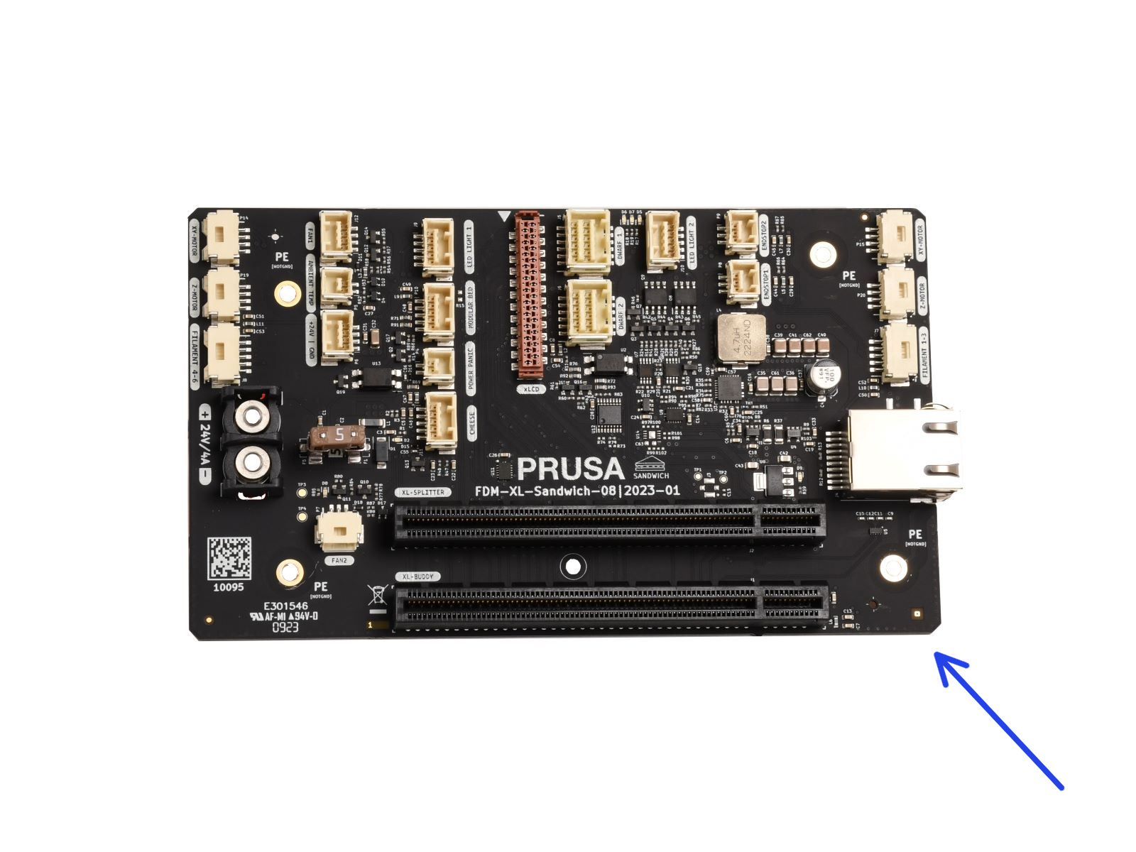
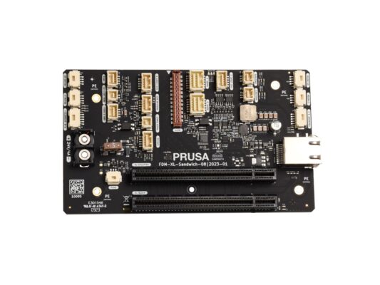
PL
  • English
  • Čeština
  • Deutsch
  • Français
Login

Jak wymienić płytkę Sandwich (XL)

Menu

Jak wymienić płytkę Sandwich (XL)

Jak wymienić płytkę Sandwich (XL)
Dotyczy:
Ostatnia aktualizacja 5 days ago
Jak wymienić płytkę Sandwich (XL)
 Poziom trudności
Średni
 Kroki
34
 Dostępne języki
ENCSDEFR
Introduction
Introduction
Ten przewodnik poprowadzi Cię przez proces wymiany płytki Sandwich w Original Prusa XL.
Poniższe instrukcje mają zastosowanie do wszystkich wersji Original Prusa XL.
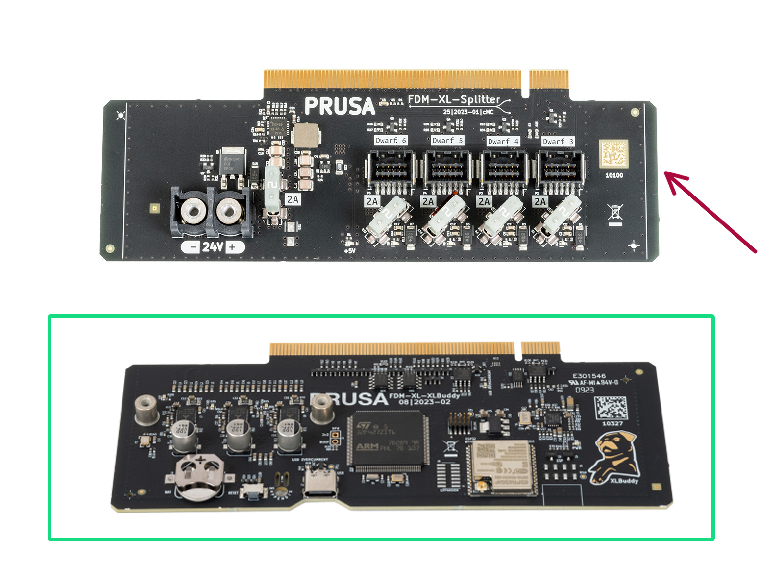
All necessary parts are available in our eshop.
Pamiętaj, że musisz się zalogować, aby mieć dostęp do sekcji części zamiennych.
Necessary tools
Necessary tools
Necessary tools
Do kolejnych etapów przygotuj:
Wkrętak/klucz Torx T10
Klucz imbusowy 2,5 mm
Wkrętak krzyżakowy PH2 (1x)
Wersje mocowania anteny Wi-Fi
The upcoming steps will vary based on the location of the Wi-Fi antenna on your printer.
Check the position of the antenna on your printer and follow the corresponding instructions:
Side mount: If the Wi-Fi antenna is on the left side of the printer (viewed from the front), proceed to Disconnecting the 1st and 2nd Nextruder cables
Rear mount: If the antenna is located at the top center on the back of the printer, proceed to the next step Detaching the Wi-Fi antenna
Cover-plug differences
Detaching the rear Wi-Fi antenna
Ten krok dotyczy drukarek z anteną Wi-Fi umieszczoną z tyłu. Jeśli w Twojej drukarce antena znajduje się z boku, pomiń ten krok.
Obróć drukarkę tylną stroną do siebie.
Zlokalizuj złącze anteny Wi-Fi z tyłu, na środku drukarki.
Odkręć antenę Wi-Fi od złącza antenowego i umieść ją w pobliżu.
Removing the electronics cover
Obróć drukarkę tylną stroną do siebie.
Using a T10 Torx key, loosen four screws securing the electronics cover.
It is not necessary to fully remove the screws.
Remove the electronics cover by sliding it upward.
After open the electronics box, you can see one of the electronics options depending on the variation of your XL printer:
Single-Tool | Dual-Head - single board electronics.
Five-Head - there is an extra board for 3rd, 4th and 5th Nextruder cables.
Disconnecting the antenna cable
Ten krok dotyczy wszystkich wersji XL - zarówno z anteną na boku drukarki, jak i z tyłu.
Znajdź i ostrożnie odłącz złącze anteny Wi-Fi.
Single-Tool | Dual-Head 
Five-Head - connected on the bottom electronics board. 
Disconnecting the 1st and 2nd Nextruder cables (rear antenna)
Proceed with this step for the printer version with rear antenna. If your printer has the antenna on the side, skip to step 8.
Uważaj, aby nie uszkodzić przewodu anteny Wi-Fi.
Każde złącze posiada zatrzask bezpieczeństwa. Przed odłączeniem należy koniecznie nacisnąć zatrzask. W przeciwnym razie może dojść do uszkodzenia złącza.
Lekko poluzuj dwie śruby mocujące pokrywę. Nie ma potrzeby wykręcania ich całkowicie. Przesuń pokrywę w prawo i wyjmij ją z drukarki.
Push the safety latch and disconnect the first Nextruder cable from the upper slot labeled DWARF 1.
Push the safety latch and disconnect the second Nextruder cable from the lower slot labeled DWARF 2.
Push the cover to the right and remove it from the printer.
Disconnecting the 1st and 2nd Nextruder cables (side antenna)
Proceed with this step for the printer version with the side antenna. If you have removed the antenna on the back of the printer, go to Disconnecting the 3rd, 4th, 5th Nextruder cables (five-tool).
Każde złącze posiada zatrzask bezpieczeństwa. Przed odłączeniem należy koniecznie nacisnąć zatrzask. W przeciwnym razie może dojść do uszkodzenia złącza.
Lekko poluzuj dwie śruby mocujące pokrywę. Nie ma potrzeby wykręcania ich całkowicie. Przesuń pokrywę w prawo i wyjmij ją z drukarki.
Push the safety latch and disconnect the first Nextruder cable from the upper slot labeled DWARF 1.
Push the safety latch and disconnect the second Nextruder cable from the lower slot labeled DWARF 2.
Disconnecting the 3rd, 4th, 5th Nextruder cables (five-tool)
This step is intended for the XL Five-Head only.
Locate the XL_splitter (electronics board to which three cables from the Nextruders are connected).
Carefully disconnect all three Nextruder cables in the following order:
Każde złącze posiada zatrzask bezpieczeństwa. Przed odłączeniem należy koniecznie nacisnąć zatrzask. W przeciwnym razie może dojść do uszkodzenia złącza.
Third Nextruder cable
Fourth Nextruder cable
Fifth Nextruder cable
Undocking the 4th and 5th Nextruders (five-tool)
Zalecamy zabezpieczenie stołu grzewczego przed kolejnymi czynnościami.
Make sure the heatbed is cooled down to ambient temperature, and the printer still turned off. Place the empty cardboard box approximately to the front center part of the heatbed.
Remove the 4th and 5th tool heads from the dock:
Remove the tool head, by pulling it outwards from the metal inserts.
Mimo, że należy spodziewać się niewielkiego oporu, ponieważ metalowe kołki są magnetyczne, używaj umiarkowanej siły.
Carefully place the removed Nextruders on the cardboard box.
Disassembling the back covers
Using a T10 Torx key, remove four M3x4rT screws from the covers.
Ostrożnie zdejmij tylną górną pokrywę przewodów [rear-cable-management-upper] i tylną dolną pokrywę przewodów [rear-cable-management-lower]. Uważaj na przewody.
Wykręć dwie śruby M3x4rT mocujące podstawę tylnej pokrywy przewodów [rear-cable-management-base] używając klucza imbusowego Torx T10, następnie zdejmij podstawę.
Removing the rear-cable-management-base is not strictly necessary, but it will help with cable management especially on a 5-tool XL.
Removing the XL_Splitter
The following step is necessary only for five-head XL. The single-tool and dual-head are not equipped with the XL_Splitter.
Touch any electronic board by its edges. Avoid damaging the board components.
Using the Philips screwdriver, release two terminal screws and disconnect both power cables.
Locate the ejectors on both sides of the electronics box. From these, locate the upper pair.
There are prepared grooves on the electronics box.
Slide out the XLSplitter. Push the ejectors so the board disconnects from the Sandwich board and then slides out using the side rails.
Removing the XL_Buddy
Touch any electronic board only by its edges. Avoid damaging the board components.
Locate the two lower ejectors.
There are prepared grooves on the electronics box.
Slide out the XL_Buddy. Push the ejectors so the board slides out from the rails.
Removing the Sandwich cables
The Molex connectors (white) have a safety latch. It is necessary to press the latch while disconnecting. Otherwise, the connector may get damaged.
Carefully disconnect the xLCD cable. Do not pull on the cable!
Disconnect all cables with Molex connector.
Using the 2.5mm Allen key, disconnect the top-right PE cable.
Using the Philips screwdriver, release two terminal screws and disconnect the power cables.
Using the 2.5mm Allen key, disconnect the bottom PE cables, and loosen the top-left M3x6 screw.
Removing the Sandwich board
In order to remove the Sandwich board, it is necessary to remove the xl-electronics-case-rail.
Start from the right side of the electronics, remove four screws using the T10 Torx screwdriver. Two screws are on the side and two are on the bottom of the box. Remove the xl-electronics-case-rail.
Touch any electronic board only by its edges. Avoid damaging the board components and touching its connectors.
Slightly tilt the Sandwich board. Then, carefully remove it from the electronics box.
Installing the new Sandwich board
Touch any electronic board only from its edges. Avoid damaging the board components and touching its connectors.
Place the replacement Sandwich board at a slight angle, then rotate it slightly to position it parallel to the rear of the printer.
Using the 2.5mm Allen key, tighten one M3x6 screw.
Using the T10 screwdriver, tighten 4 M3x8rT screws, two on the side and two on the bottom of the box, to install the xl-electronics-case-rail.
Connecting the Sandwich cables (part 1)
Using the 2.5mm Allen key, tighten the M3x6 screw to connect the bottom-right PE cable.
Using the 2.5mm Allen key, tighten the M3x6 screw to connect the bottom-left PE cable.
Using the Philips screwdriver, connect the power cables.
Positive
Negative
Double-check the correct polarity (positive-negative) of the above cables
Ensure that all screw-attached connectors are completely tightened.
Connecting the Sandwich cables (part 2)
Connect the following cables from the right side:
XY-left motor
Z-left motor
Side filament sensor (left, tools 1-3)
Using the 2.5mm Allen key, tighten a M3x6 screw to connect the top-right PE cable.
Ensure that all screw-attached connectors are completely tightened.
Connect the LED light cable 2.
Connecting the Sandwich cables (part 4)
Connect the rest of the cables from the left side:
LED Lights 1
Modular Bed
Power panic
Double-check the LED lights and the Modular Bed connections by verifying their cable colors.
Złącze przewodu xLCD posiada zatrzask blokujący, który musi być skierowany w stronę czerwonego trójkąta znajdującego się w pobliżu gniazda xLCD.
Connect the xLCD cable
Installing the XLBuddy
Uważaj, aby nie przygnieść przewodów!
Touch any electronic board only from its edges. Avoid damaging the board components.
Po bokach obudowy płyty XL Buddy [XL-buddy-box] znajdują się przygotowane rowki prowadzące.
Using both hands, insert the XL-Buddy into the slot in the XL-sandwich-board.
Installing the XL_splitter (five-head)
The following step is necessary only for five-head XL. The singe-tool and dual-head are not equipped with the XL_Splitter.
Uważaj, aby nie przygnieść przewodów!
Touch any electronic board only from its edges. Avoid damaging the board components.
Po bokach obudowy płyty XL Buddy [XL-buddy-box] znajdują się przygotowane rowki prowadzące.
Używając obu rąk, wsuń płytkę XL-splitter w gniazdo w płytce XL-sandwich.
Weź przewód zasilający i ułóż go po lewej stronie obudowy płyty XL Buddy [XL-buddy-box].
Umieść czarny przewód na lewym zacisku i dokręć śrubę zacisku.
Umieść czerwony przewód na prawym zacisku i dokręć śrubę zacisku.
Note the correct orientation of the power cable connectors.
Connecting the 3rd, 4th, 5th Nextruder cables
Nie wyciągaj płytki XL-splitter z drukarki - zdjęcie jest jedynie ilustracją kolejności podłączenia przewodów Nextruderów.
Connect the Nextruder cables to the splitter in the following order:
Third Nextruder.
Fourth Nextruder.
Fifth Nextruder.
Płytka XL-splitter z podłączonymi Nextruderami powinna wyglądać tak, jak na ilustracji.
Przegląd okablowania elektroniki
Before proceeding to the next step, check the cable connections according to the picture.
Double-check all the connections before proceeding to the next step.
Pokrywa elektroniki: przygotowanie części
XL-buddy-box-cover (1x)
Rear-cable-management-upper (1x)
Rear-cable-management-base (1x)
M3x5rT screws (4x)
M3x4rT screws (2x)
Either of the following two parts depending on the antenna mount position:
Antenna-holder with antenna cable (1x), rear-antenna version
Rear-cable-management plug (1x), side-antenna version
Covering the electronics (part 1)
Uważaj, aby nie przygnieść przewodów!
Z lewej strony nałóż podstawę tylnej pokrywy przewodów [rear-cable-management-base] i przykręć ją dwiema śrubami M3x4rT używając klucza Torx T10.
Covering the electronics (part 2)
Uważaj, aby nie przygnieść przewodów!
Ostrożnie przymocuj tylną-górną pokrywę przewodów [Rear-cable-management-upper].
Upewnij się, że żaden przewód nie jest przyciśnięty między plastikowymi pokrywami.
Upewnij się, że metalowa pokrywa nie przyciśnie przewodu silnika.
Przymocuj ją czterema śrubami M3x5rT używając wkrętaka T10.
If your printer has its antenna on the side, check if the XL-rear-cable-management-plug is installed.
Loosen two bolts using the T10 screwdriver, and remove the XL-rear-cable-management-plug.
Connecting the 1st and 2nd Nextruder cables
Connect the first Nextruder cable to the upper slot labeled DWARF 1.
Connect the second Nextruder cable to the lower slot labeled DWARF 2.
If your printer had the antenna located on the side, proceed with the following point.
Attach the cover (xl-rear-management-plug) onto the screws. Push the cover all the way to the left and tighten the screws.
If your printer had the antenna located on its rear side, proceed to the next step.
Installing the Wi-Fi antenna cover (rear antenna)
This step is valid only if your printer has its Wi-Fi antenna on the back of the printer. If you have the antenna on the side of the printer, proceed to the next step.
Przełóż przewód antenowy przez otwór w blaszanej pokrywie złączy i poprowadź go za blachą do obudowy elektroniki.
Włóż uchwyt anteny na śruby, przesuń w lewo i dokręć śruby.
Montaż pokrywy XL Buddy
Be careful, do not pinch any cables!
Załóż pokrywę Buddy XL (XL-buddy-box-cover) z powrotem na drukarkę.
On the five-head XL, check the Nextruders cables, they have to be inside the cutout in the cover.
Dokręć cztery śruby używając wkrętaka T10.
Docking the 4th and 5th Nextruders (five-tool)
Zalecamy zabezpieczenie stołu grzewczego przed kolejnymi czynnościami.
Dock the 4th and 5th Nextruders.
Weź Nextruder i umieść go ostrożnie obok doku.
Wsuń dwa metalowe kołki przez białe otwory w doku. Magnesy pomogą zadokować Nextruder.
Remove the previously placed cardboard box from the printer heatbed.
Performing the Calibration Wizard
Po uruchomieniu drukarki na ekranie pojawi się monit o uruchomienie kreatora testów i konfiguracji drukarki.
Kreator przetestuje wszystkie ważne komponenty drukarki. Cały proces zajmuje kilka minut. Niektóre części kreatora wymagają bezpośredniej interakcji użytkownika. Postępuj zgodnie z instrukcjami wyświetlanymi na ekranie.
UWAGA: podczas testowania osi upewnij się, że w drukarce nie ma niczego, co utrudnia ich ruch.
UWAGA: nie dotykaj drukarki w trakcie pracy kreatora, chyba że pojawi się odpowiedni monit! Niektóre części drukarki mogą być GORĄCE i mogą poruszać się z dużą prędkością.
Follow the steps in the dedicated manuals, specific for your version of Original Prusa XL.
Czy ten poradnik był pomocny?

Komentarze

Wciąż masz pytania?

Wciąż masz pytania?

Jeśli masz pytanie dotyczące czegoś, czego nie opisaliśmy, to sprawdź dodatkowe zasoby.
A jeśli to nie działa, możesz wysłać zgłoszenie na [email protected] lub klikając poniższy przycisk.

Kontakt