ES
  • English
  • Čeština
  • Italiano
  • Deutsch
  • Polski
  • Français
Iniciar sesión

9A. MK4/S, MK3.9/S Nextruder mod

9A. MK4/S, MK3.9/S Nextruder mod

9A. MK4/S, MK3.9/S Nextruder mod
Relevante para :
Ultima actualización a month ago
9A. MK4/S, MK3.9/S Nextruder mod
 Dificultad
Muy difícil
 Pasos
29
 Obtén el manual completo en formato PDF
Descargar
 Idiomas disponibles
ENCSPLDEITFR
Introduction
Introduction
Introduction
In this guide, we’re going to modify the Nextruder on your MK4/S, MK3.9/S to accomodate the MMU functionality.
If you are using another printer type, please refer to the respective chapter for the given printer.
The MK3.9/S printer is functionally equivalent to the MK4/S.
The instructions are shown using the MK4 printer, so some parts may look different. This does not affect the procedure.
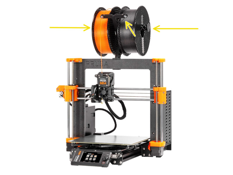
Descarga el filamento de la impresora y retira el portabobinas.
Make sure the extruder on your printer is in the middle of both the X and Z axes.
Power off your printer and disconnect it from the power.
Spare parts bag
Spare parts bag
During the conversion of the Nextruder to the multi-material version, you'll handle many parts that look similar but are different. We recommend setting aside a bag for spare parts to store components that won't be needed anymore.
Rest assured, our guide will clearly indicate which parts will be reused and which won't.
Let’s begin!
Prusa Nozzle info (MK4S only)
There are two variants of the Prusa Nozzle that we ship with the printers:
Prusa Nozzle brass CHT high flow (marked CHT)
Prusa Nozzle brass (marked PR)
If you own an MK4S, your printer comes equipped with a Prusa Nozzle CHT by default. However, when using the MMU3, we recommend switching to a standard Prusa Nozzle for optimal performance.
While it is possible to print with the Prusa Nozzle CHT, please note that specific settings are required to achieve high-quality prints.
The standard Prusa Nozzle is included in your MMU3 package.
To replace the nozzle on the MK4S, please follow the instructions provided in the dedicated manual How to replace the Prusa Nozzle (MK4S/MK3.9S).
Once completed, return to this manual to continue with the assembly.
Nextruder disassembly (part 1)
Remove the top Loveboard-cover from the extruder by pulling it up.
Open the Idler swivel.

Fully loosen the M3x25 screws holding the gearbox cover. 

Leave the screws in place. Do not remove them entirely yet.

There were multiple versions of the Nextruder. The earlier models have four screws on the front. The newer model has three screws.
Nextruder disassembly (part 2)
Remove the whole gearbox assembly from the Nextruder.
Locate the metal washer that should be between the gearbox and the motor. It might be stuck to the gearbox assembly.
Earlier versions of the Nextruder use an orange spacer instead of the metal washer.
Reseat the washer / spacer on the motor shaft, in case it has come off the shaft.
The parts might be greasy. Clean off any excess grease.
Nextruder disassembly (part 3)
Con la llave Allen de 1.5mm, retira el tornillo prisionero.
If you own the 4-screw version of the Nextruder, this specific type of set screw is not included.
Remove the Idler.
Remove the two M3x30 screws with the springs.
Remove the idler swivel assembly.
Nextruder disassembly (part 4)
On top of the Nextruder heatsink, there is a filament sensor assembly. We will need to remove it.
Using the needle-nose pliers, gently pull the filament sensor assembly out of the heatsink.
Proceed very carefully, there is a spring and a very tiny ball that can fall out!
En caso de que el conjunto del sensor de filamento sea difícil de extraer, introduce la llave Allen de 2.5 mm en la abertura del filamento situada en la parte superior para empujar la bola de acero del interior del conjunto hacia dentro. A continuación, extrae el conjunto del sensor de filamento.
This filament sensor assembly will not be used with the multi-material Nextruder. It's recommended to store it in a spare parts bag.
Idler disassembly
Idler disassembly
Idler disassembly
We will need to take the Idler assembly apart.
Remove the M3x6 screw.
Split the printed parts to open it up.
Set aside for later use: Bearings, pins, spacer and the screw.
The printed parts won’t be re-used. Set them aside so that they don’t mix up with the new parts.
New Idler parts preparation
Para los siguientes pasos, por favor prepara:
Idler-lever-a (1x) the new part
Idler-lever-b (1x)  the new part
The older Idler printed parts, made from PETG, are prone to bending over time. Do not reuse these old parts, as they may cause the printer to malfunction.
Bearing 693 2RS (2x) you removed earlier
Pin 2.9x8.5 (2x) you removed earlier
M3x6 screw (1x) you removed earlier
Spacer tube 13.2x3.8x0.35 (1x)  you removed earlier
New Idler assembly
New Idler assembly
New Idler assembly
New Idler assembly
Take the new Idler-lever-a part.
Insert the two pins into the corresponding openings.
Mount the bearings onto the pins.
Cover the assembly with the Idler-lever-b part.
Insert the spacer tube into the corresponding opening.
Fix the assembly together using the M3x6 screw.
Swivel disassembly
Swivel disassembly
Swivel disassembly
Swivel disassembly
We will need to take the Swivel assembly apart.
Using the T10 Torx key, remove the screws while you hold the nuts using the needle-nose pliers.
Set aside for later use: M3nN nuts and spacer.
The printed parts and the screws won’t be re-used. Set them aside so that they don’t mix up with the new parts.
Idler nut FS parts preparation
Para los siguientes pasos, por favor prepara:
Idler nut FS (1x) the new part
Magnet 3x1mm (1x)
There are two of these tiny magnets included in the package. Please separate them and use only one; the other magnet serves as a spare.
Idler nut FS assembly
Arrange the Idler nut FS part as seen in the picture.
Install the tiny 3x1mm magnet into the marked opening on the Idler nut FS part.
Push the magnet all the way in, until it stops.
The polarity / orientation of the magnet isn't important. The printer will automatically adapt to it during the filament sensor calibration process.
New Swivel parts preparation
Para los siguientes pasos, por favor prepara:
Idler nut FS (1x) with the 3x1mm magnet installed
Swivel B (1x) the new part
Swivel A (1x) the new part
M3nN nut (2x) you removed earlier
Spacer 6x3.1x8 (1x) you removed earlier
M3x22 screw (2x)
This screw is a new type not previously used on a printer! Do not reuse old screws, as they are a different size and would not fit properly!
New Swivel assembly (part 1)
Take the Swivel A part and orient it as seen in the picture.
Insert the M3x22 screw into the opening near the thick part of the Swivel A.
Slide the spacer onto the screw.
Insert the second M3x22 screw into the other opening on the side.
Slide the Idler nut FS part onto the M3x22 screw.
New Swivel assembly (part 2)
Orient the Swivel assembly as seen in the picture.
There is a tiny magnet in the Idler nut FS part. Make sure it is in place.
In case  the magnet has fallen out, there is a replacement one in the package.
Slide the Swivel B part onto the screws.
Attach the M3nN nuts onto the screws. Tighten the screws gently while holding the nuts using the neeedle-nose pliers.
Do not overtighten the nuts. The Swivel must be able to move freely.
Tension screws parts preparation
Para los siguientes pasos, por favor prepara:
M3x30 screws with the springs (2x) you have removed earlier
We will need the springs alone. The old M3x30 screws won’t be re-used.
Remove the springs from the old M3x30 screws.
M3x35 screws (2x) the new, slightly longer ones.
This screw is a new type not previously used on a printer! Do not reuse old screws, as they are a different size and would not fit properly!
Screw guide (1x)
Tension screws assembly
Take the new M3x35 screws.
Compare the size of the screws. Set the old M3x30 and the new M3x35 screws apart so that they don’t mix up.
The old shorter M3x30 screws won’t be re-used.
Push the M3x35 screws through the screw guide.
Attach the springs onto the end of both the screws.
Gearbox disassembly
Gearbox disassembly
Gearbox disassembly
Take the gearbox assembly and split it apart.
The parts might be greasy. Clean off any excess grease.
Set aside for later use: PG-case, PG-ring, PG-assembly, M3x25 screws.
The printed main-plate won’t be re-used. Set it aside so that it doesn’t mix up with a new part.
Main plate parts preparation
Para los siguientes pasos, por favor prepara:
new Main Plate (1x)

We will need the newly supplied main-plate. 

It is different than the original one in the gearbox assembly, printed from PETG. Do not reuse the old main plate, as it may cause the printer to malfunction!

The new main plate is 3D printed using MJF technology. It cannot be replicated with the same quality using FDM printing.
O-ring 24,5x1,5 (1x)
Main plate assembly
Main plate assembly
Main plate assembly
There is a V-shaped groove on the inside of the large round opening on the new main-plate.
Insert the O-ring into the groove. Make sure it is seated properly.
MMU Nextruder: parts preparation
Para los siguientes pasos, por favor prepara:
Set screw M3x25 (1x)
If you own the 4-screw version of the Nextruder, this specific type of set screw is not included.
Tension screws assembly (1x)
Swivel assembly (1x)
Idler assembly (1x)
Main plate assembly (1x)
PG-assembly (1x)
MMU Nextruder assembly (part 1)
Add the Idler assembly onto the extruder.
Fix it in place using the M3x25 Set screw.
In case you have the 4-screw version of the Nextruder, you might use the M3x25 screw to temporarily hold the Idler assembly in place.
Add the Swivel assembly onto the extruder. The protruding part of the Idler nut FS component should fit inside the filament sensor pocket in the heatsink, as seen in the picture.
MMU Nextruder assembly (part 2)
Insert the tension screw assembly through the heatsink and direct it towards the Swivel assembly.
Tighten the tension screws gradually, one at a time, until the ends of the screws are flush with the surface of the Idler nut part on the opposite side, as shown in the picture.
MMU Nextruder assembly (part 3)
Attach the new main plate assembly to the extruder, ensuring the protruding parts fit correctly into the heatsink.
The notch in one of the corners is designed to fit over the Idler spacer / set screw.
Ensure the lever on the Swivel assembly fits correctly into the cutout on the main plate.

Attach the PG-assembly to the motor shaft. Be very careful when inserting the assembly into the opening with the O-ring. Watch out for any deformation or damage to the O-ring. Ensure the O-ring stays properly seated in its groove on the main plate. A slight wiggling motion can assist with this.

Watch out for any deformation or damage to the O-ring. Ensure the O-ring stays properly seated in its groove on the main plate. A slight wiggling motion can assist with this.
Gearbox assembly: Parts preparation
Para los siguientes pasos, por favor prepara:
PG-assembly adapter (1x)
PG-ring (1x)
M3x25 screws (3x or 4x depending on the Nextruder version)
PG-case assembly (1x)
Gearbox assembly (part 1)
Attach the adapter to the PG-assembly, making sure the spur gears are correctly aligned and fit snugly into the pockets on the adapter.
Carefully slide the PG-ring onto the adapter, pushing it all the way in gently, until it locks onto the gears.
Note there is a chamfer on one side of the PG-ring. This side should be facing the gears, while inserting the PG-ring.

Gently rotate the adapter while sliding the PG-ring onto the gears to align the gearbox properly.

Retira el adaptador, mientras sujetas la caja de engranajes en su lugar.
Gearbox assembly (part 2)
Check the PG ring for adequate lubrication. If necessary, apply a slight amount of grease, similar to the procedure for the MK4 kit.
Cover the gearbox using the PG-case.
Secure the case using the M3x25 screws. Do not overtighten the screws!
Attach the top Loveboard cover back onto the extruder.
¿Fue útil esta guía?

Comentarios

¿Todavía tienes preguntas?

¿Todavía tienes preguntas?

Si tienes alguna pregunta sobre algo que no se ha tratado aquí, comprueba nuestros recursos adicionales.
Y si eso no lo soluciona, puedes enviar una petición a info@prusa3d.com o mediante el botón que hay más abajo.

Contacta con nosotros