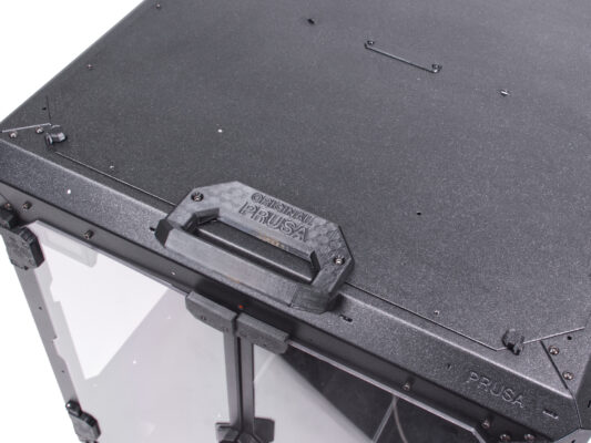
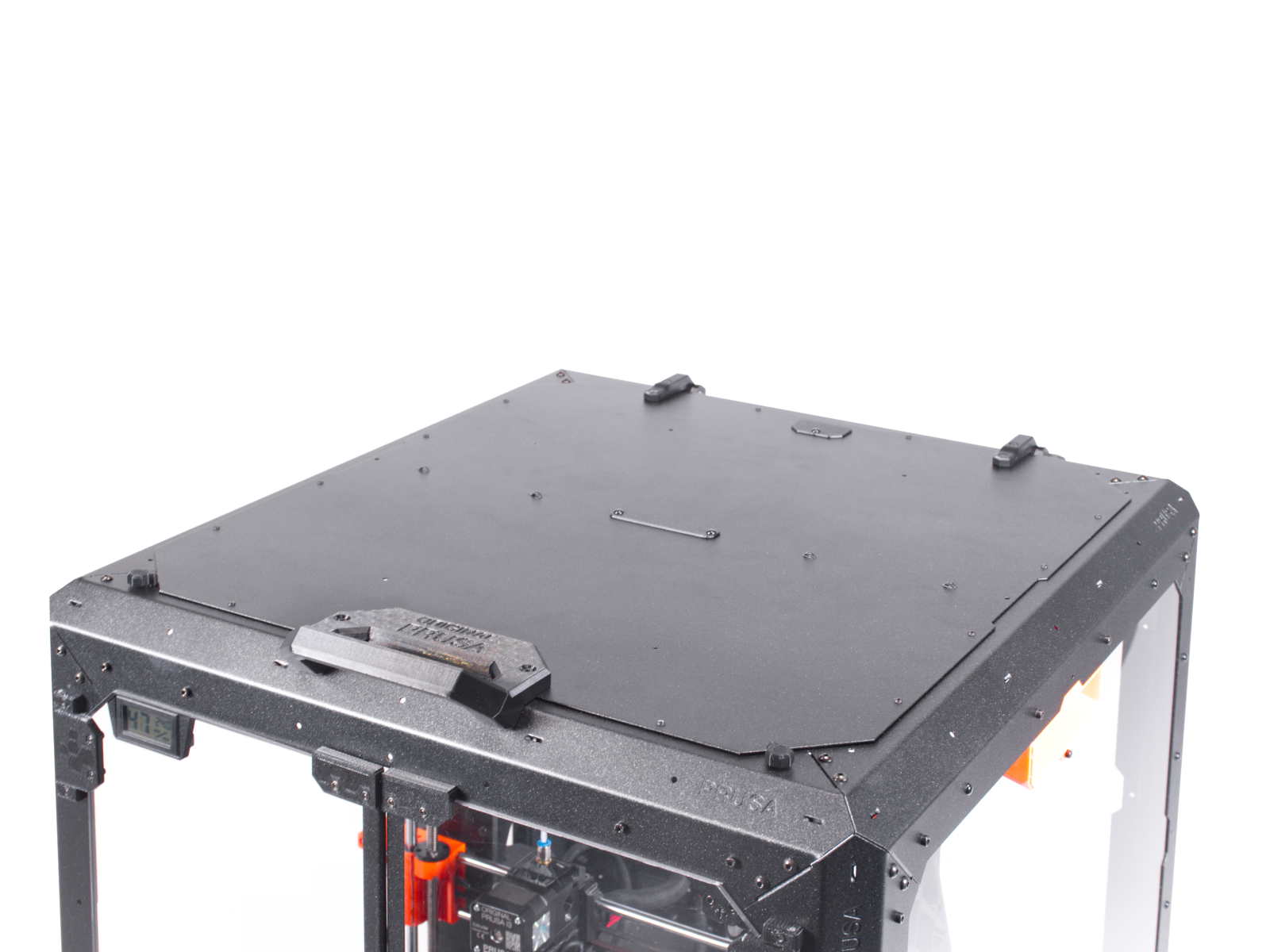
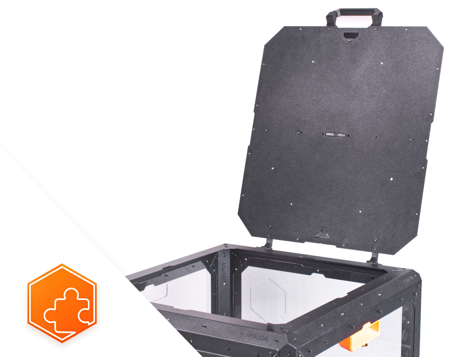
EN
  • Čeština
  • Español
  • Italiano
  • Deutsch
  • Polski
  • Français
Login

6. Hinged Lid (add-on)

Menu

6. Hinged Lid (add-on)

6. Hinged Lid (add-on)
Relevant for:
Last updated 8 months ago
6. Hinged Lid (add-on)
 Difficulty
Easy
 Steps
42
 Available languages
CSPLDEESITFR
Introduction
Introduction
Introduction
This guide will take you through the installation of the Hinged lid on the Original Prusa Enclosure.

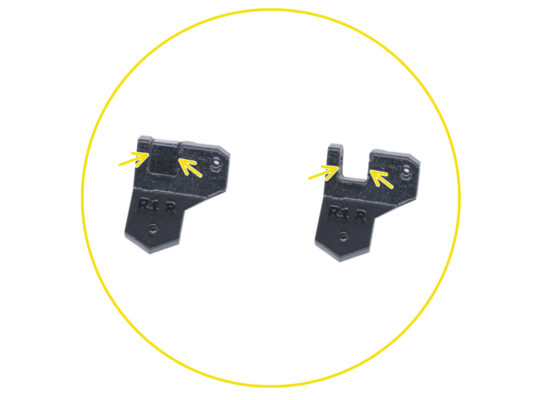
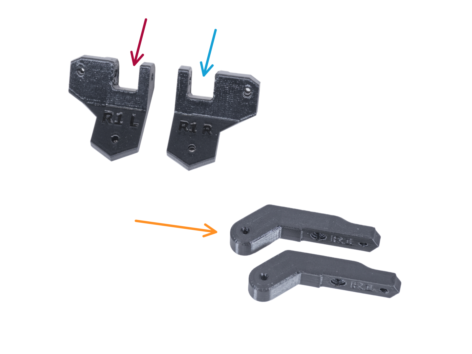
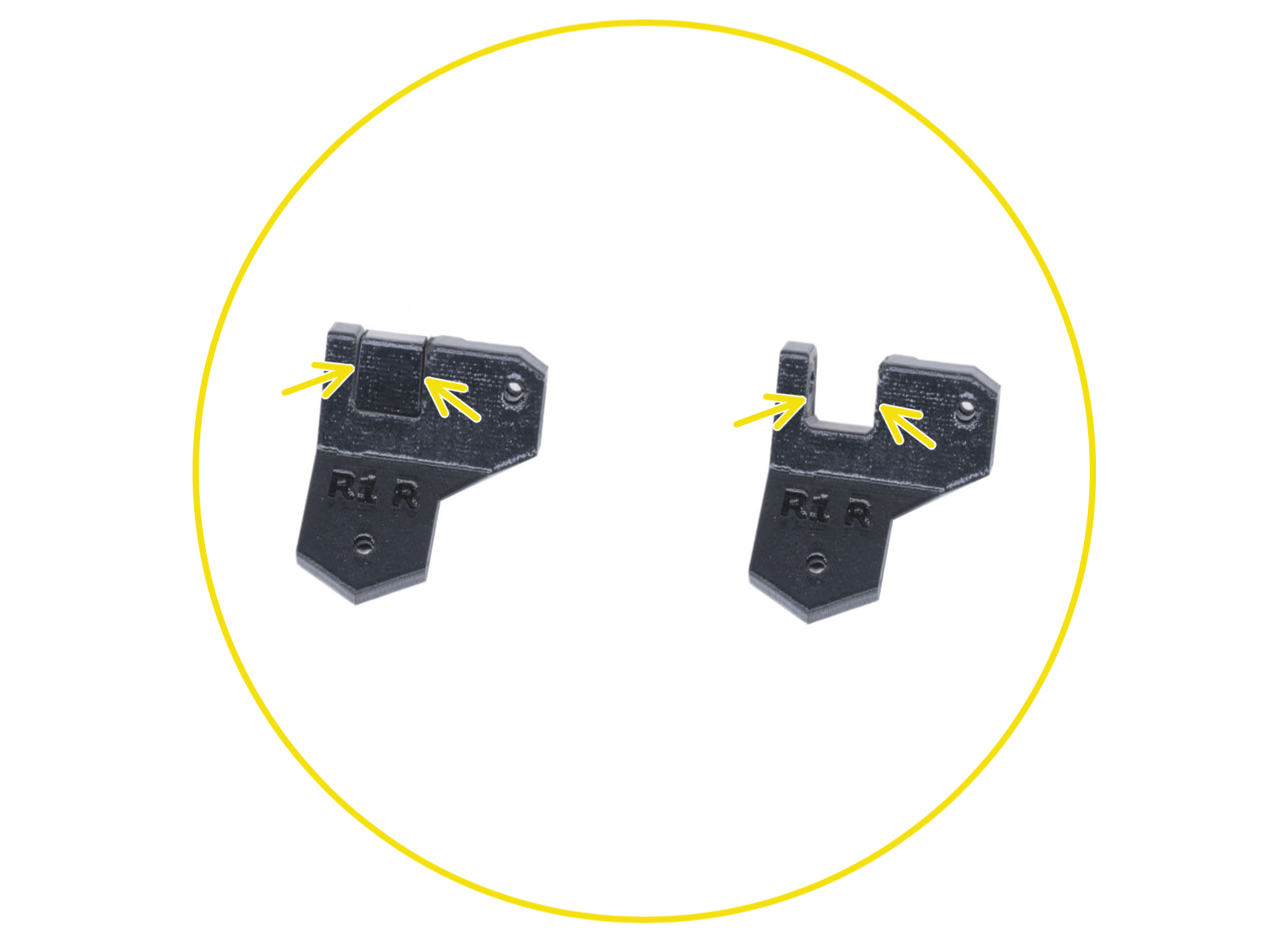
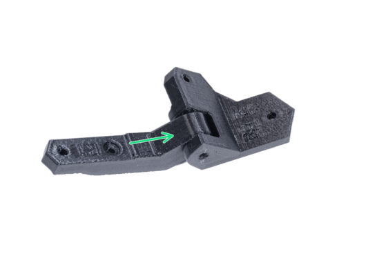
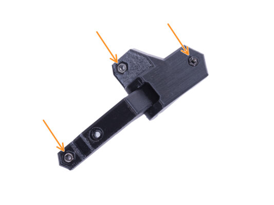
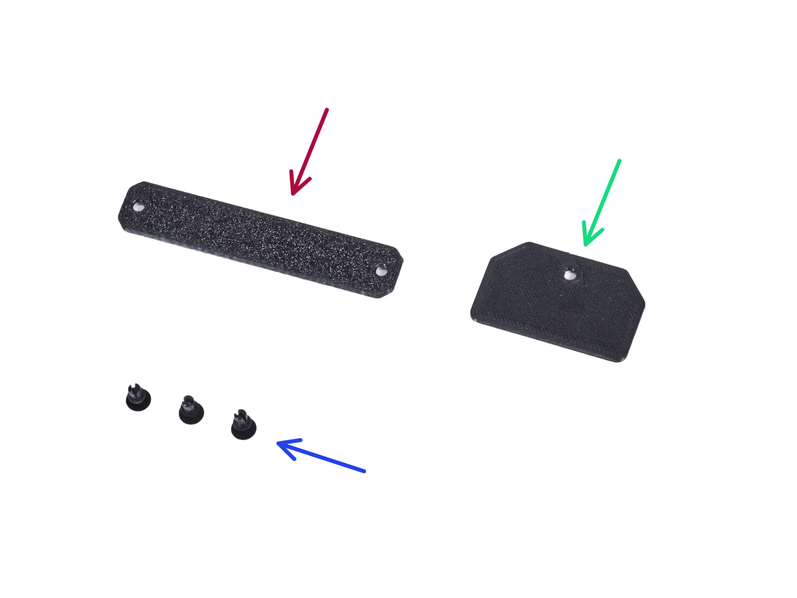
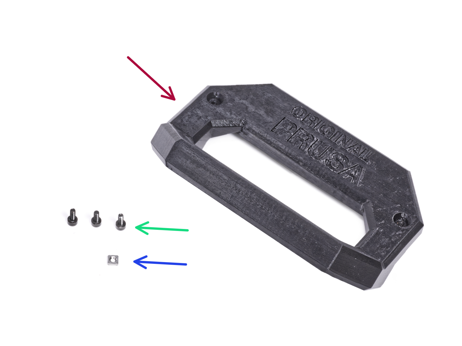
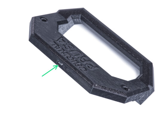
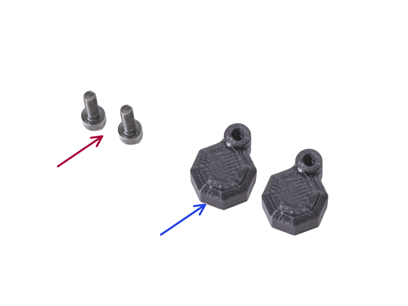
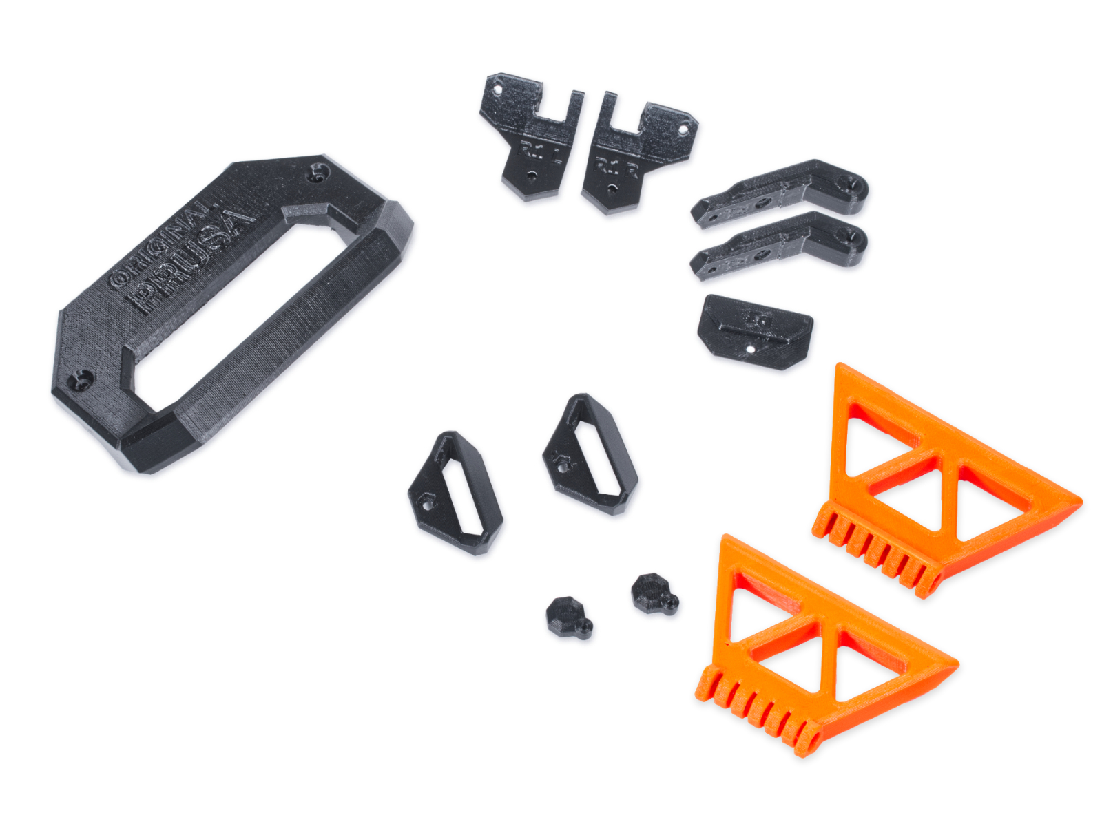
Before you start installing the add-on, PRINT OUT ALL NECESSARY PLASTIC PARTS! The parts are available for download at Printables.com.

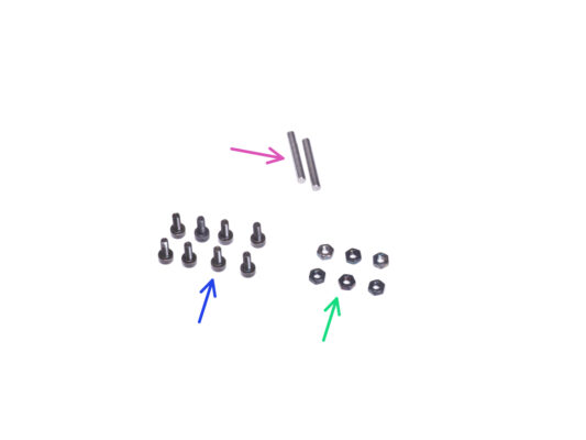
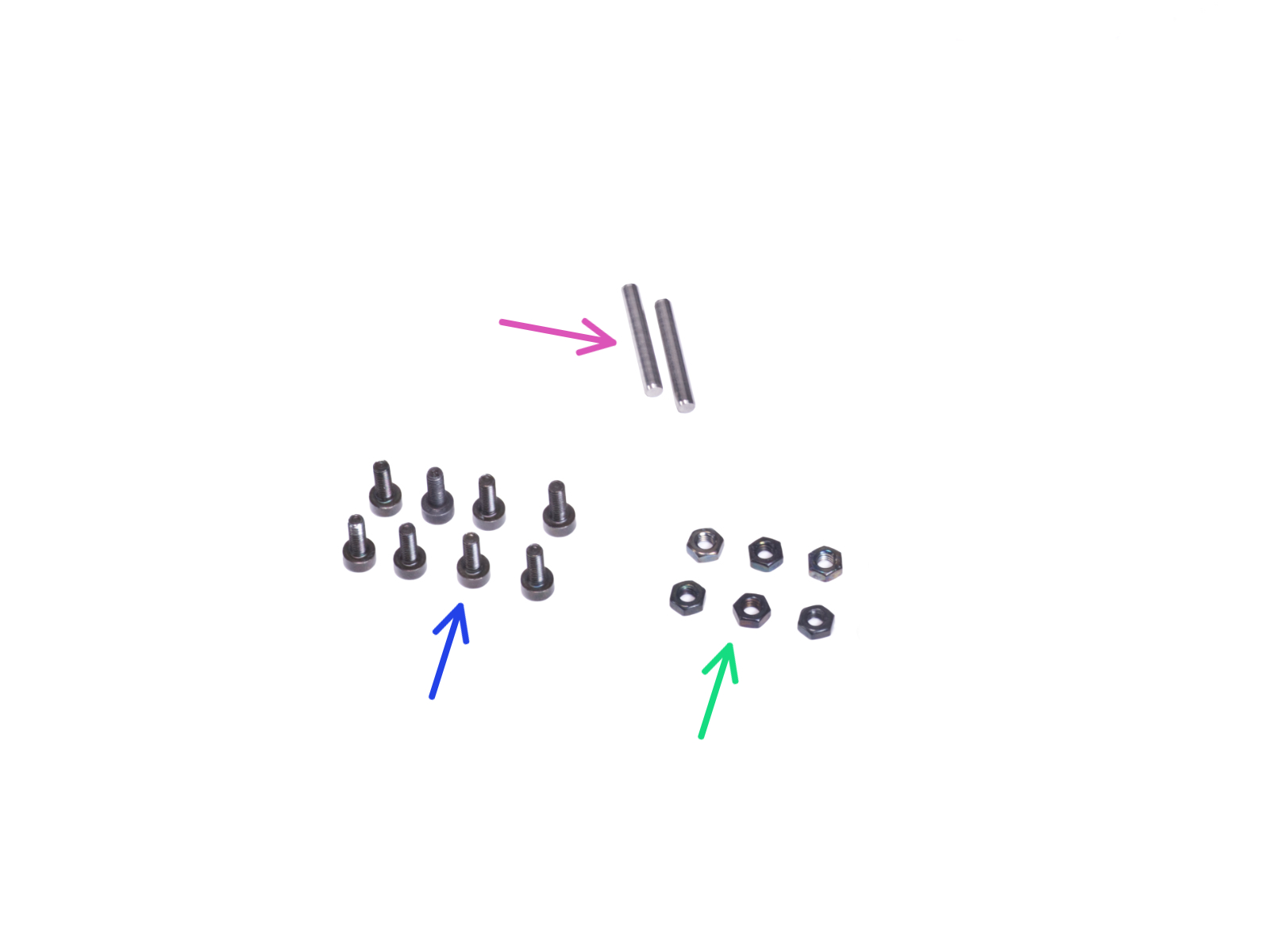
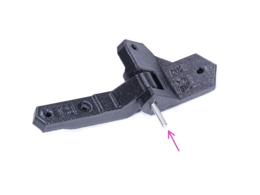
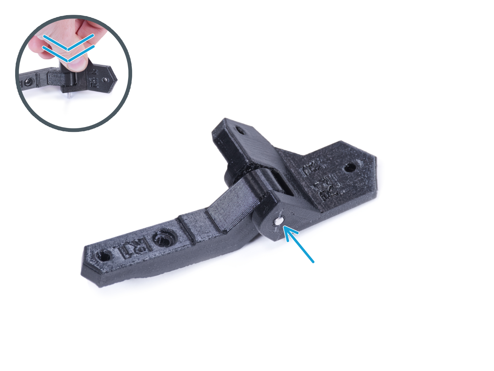
All necessary fasteners are already included in the Enclosure kit.
Tools necessary for this chapter
For this chapter, please prepare:
2.5mm Allen key
Needle-nose pliers
Pocket knife or snap-off knife (for MMU installation only)
Removing the covers
Removing the covers
Removing the covers
From inside, push out the nylon rivet securing the Top-plug-edge in the front of the enclosure. Use the needle-nose pliers to push on the nylon rivet.
Remove the Top-plug-edge part from the enclosure.
Using the same procedure remove the Top-plug-edge on the rear side.
Remove the Top-plug-center part. Do not discard this part, you will need it later again.
Removing the top panel
Release thirteen screws on the top frame.
Keep the three screws in the positions marked in the picture.
From inside, support the top panel with your hand.
Using the other hand release the three screws securing the top panel while holding the panel.
WARNING: Be careful not to drop the top panel and cause injury or damage!
Push out the top panel through the top frame opening and remove it from the enclosure.
Installing the lid hinges: parts preparation
For the following steps, please prepare:
Hinge-bracket-L (1x)
Hinge-bracket-R (1x)
Note that, after printing, both the hinge brackets have an internal support structure which needs to be removed before use. See the last picture.
Hinge-lever (2x)
Pin 3x20 (2x)
M3x8 screw (8x)
M3n nut (6x)
Assembling the lid hinges
Insert the Hinge-lever into the Hinge-bracket-R.
Align the holes in both parts and push the pin 3 x 20 into the plastic parts.
Against the flat surface, push the pin all the way into the plastic parts. Make sure the pin is flush with the surface of the part.
Proceed the same for the Hinge-bracket-L.
Installing the lid hinges
Turn the enclosure with the rear side facing you. And focus on the left top corner.
From inside, push out the first nylon rivet from the left.
Use the needle-nose pliers to push on the nylon rivet.
Into the same hole, insert the M3x8 screw from the inside.
Attach the Hinge-bracket-R assembly to the screw and tighten it.
If you have installed the Advanced filtration system add-on, use the hinge-bracket-Rt available on printables.com
Installing the lid hinges
Focus on the right top cornet on the rear side of the enclosure.
From inside, push out the first nylon rivet from the right.
Use the needle-nose pliers to push on the nylon rivet.
Into the same hole, insert the M3x8 screw from inside.
Attach the Hinge-bracket-L assembly to the screw and tighten it.
Installing the lid hinges
Secure the Hinge-bracket-L with the M3x8 screw from the inside.
Secure the Hinge-bracket-R with the M3x8 screw from the inside.
Open both hinges.
Installing the top panel
Place the top panel on the top of the enclosure and make sure that:
Perforations on the top panel are facing up.
The side with the more distant threaded columns is at the rear (close to the hinges).
Close the hinges and secure each hinge with the M3x8 screw.
Open the lid (top panel) and secure each hinge with the M3x8 screw from the underside.
Installing the covers
Place the Top-plug-center on the rectangular hole in the top panel and secure it with two nylon rivets.
Place the Top-plug-rear to the cutout on the rear side of the top panel and secure it with the nylon rivet.
Mounting the handle
Mounting the handle
Mounting the handle
Mounting the handle
Insert the M3nS nut all the way into the Lid-handle.
Attach the Lid-handle to the top panel on the front edge and secure it with two M3x8 screws.
Do not overtighten the screws! It can damage the thread in the metal sheet.
Open the lid and secure the handle from inside using the third M3x8 screw.
Mounting the locks
Mounting the locks
Mounting the locks
Mounting the locks
Turn the enclosure with the front side facing you and focus on the right top corner.
From inside, insert one M3x8 screw through the first hole from the left on the top front profile.
Attach one of the Lid-lock to the screw and tighten it. Do not over tighten the screw. The lock must rotate freely.
Proceed the same with the second Lid-lock.
Locking the locks
Locking the locks
Locking the locks
Close the lid and turn both Lid-lock. If the locks turn stiffly over the lid, slightly loosen the screws on the bottom of the lock (inside the enclosure).
What else?
What else?
Good job! You successfully installed the hinged lid on the Original Prusa Enclosure.
If you intend to use a single-material printer, your work is done here. For the installation of the MMU2S into the Original Prusa Enclosure continue with the following steps.
Removing the LCD
Removing the LCD
Removing the LCD
Removing the LCD
Carefully cut the zip tie securing the LCD cable bundle.
Release two screws mounting the LCD assembly.
Disconnect both LCD cables from the LCD.
Push the LCD cable bundle through the hole in the bottom panel into the enclosure.
Removing the filament guide
Press down the blue collet on the Fitting QSM-M5.
Pull out the PTFE tube from the fitting.
Cut the zip tie securing the PTFE tube on the inner side of the top front profile.
Release two screws mounting the filament guide and remove it from the enclosure.
Removing the printer
The following instructions will show the MK3S+ with a black PSU. However, the procedure for the silver PSU is identical.
Place the printer at an angle (as shown in the picture) in the enclosure behind the anti-slip dampers.
"Unlock" all PSU-locks and grasp the PSU assembly by its handle and remove it from the back panel.
Place the PSU on the heatbed protected with the cloth. Turn it with the PSU-handle facing upwards.
Removing the printer
Open the lid.
Grasp the printer by its frame and carefully remove it from the enclosure.
Avoid scratching the printer and enclosure.
Installing the MMU2S
Now, proceed to the instructions for installing the MMU2S unit on the printer.
The procedure will vary slightly depending on whether the MMU2S unit was only temporarily removed from the printer during the enclosure assembly, or whether it was never installed on the printer at all. Choose your option:
Brand new installation of the MMU2S unit on the printer: go to Original Prusa i3 to MMU2S upgrade manual.
Re-mounting the MMU2S unit to the printer: go to  Assembling the MMU2S unit.
After you have finished installing the MMU2S unit on the printer, return to this guide and continue with the next step.
Preparing the printer (MK3S+ with MMU2S)
Before you place the printer in the enclosure, make sure it is prepared in this state:
LCD is disconnected and removed from the printer
PSU (both black and silver version) is removed from the frame and placed on the protected heatbed
The printer frame support is installed on the printer
Installing the printer
Grasp the printer by its frame and carefully insert it into the enclosure. Insert the printer slightly diagonally so as not to scratch the printer and enclosure.
Avoid placing the printer on cables and PTFE tubes!
Place the printer at an angle (as shown in the picture) in the enclosure behind the anti-slip dampers.
It's just a temporary position for the printer. We will adjust the correct position later.
Installing the PSU
Installing the PSU
Installing the PSU
Installing the PSU
From inside the enclosure, grasp the PSU by its handle in your hand.
It is more convenient to use the right hand.
Insert the PSU through the hole at the bottom of the back panel. Start by pushing through the part with the PSU-retainer (the part with the magnets).
Tilt the PSU towards the back panel. The PSU must be outside the enclosure and the PSU holder inside the enclosure.
The PSU holder must fit perfectly on all four PSU-locks.
Turn all PSU-lock 90° to lock the PSU assembly.
Adjusting the printer
Rearrange position of the printer like in the picture. Place it in the center of the enclosure and adjust the correct position:
The two rear anti-slip dampers must be locked against the rear plate from the inside.
The two front anti-slip dampers must be locked from the outside by the front plate.
Guide the LCD cable bundle under the printer from the electronics to the front side of the enclosure. Leave the cable free for now.
Mounting the LCD
Mounting the LCD
Mounting the LCD
Mounting the LCD
Guide the LCD cable through the cutout in the bottom panel.
Secure the textile sleeve on the cable bundle with the zip tie. Do not over tighten the zip tie, it may cut the cables!
From the inside, push two M3x8 screws through the bottom profile.
Place the LCD assembly close to the LCD cables, like in the picture. Mind the same orientation of the LCD as in the picture. See the LCD-supports for better understanding.
Note that both cables are marked with stripes on one side. Correct connection order is important!
Connect the LCD cable marked with TWO STRIPES to the left slot (called EXP2) on the LCD controller.
Connect the LCD cable marked with ONE STRIPE to the right slot (called EXP1)  on the LCD controller.
Slide the LCD assembly onto the two M3x8 screws in the frame and tighten them.
Assembling the MMU-grommets
There are two symmetrical grommets for both edges of the enclosure's rearside. In case you intend to place all spools only on one side outside the enclosure, you can use just one grommet.
Using the Allen key, remove the print support from both MMU-grommets.
Insert the M3n nut into each MMU-grommet.
Mounting the MMU-grommets
Depending on where you will place your spools, cut out the left, right, or both sides.
From inside of the enclosure, use the knife and CAREFULLY cut off all supports of the left grommet cutout on the back panel and remove it.
From inside of the enclosure, use the knife and CAREFULLY cut off all supports of the right grommet cutout on the back panel and remove it.
Mounting the MMU-grommets
From inside, push the M3x8 screw through the hole next to the left grommet cutout.
From the outside, attach the MMU-grommet in the same orientation to the cutout and the screw. Tighten the screw.
Mounting the MMU-grommets (optional)
From inside, push the M3x8 screw through the hole next to the right grommet cutout.
From the outside, attach the MMU-grommet in the same orientation to the cutout and the screw. Tighten the screw.
Guiding the PTFE tubes
Merge all PTFE from the MMU2S and push them through the right MMU-grommet out of the enclosure.
You can use the left MMU-grommet as well. The procedure is the same.
Assembling the buffer feet
Release two screws securing the s-buffer-hook-uni and remove the printed part from the buffer.
Insert the screw into the nut in the s-buffer-hook-uni. Do not screw it completely, a few turn are enough.
Pull the screw and the nut out of the printed part. Take off the nut from the screw.
If it is difficult to pull the nut this way, take the spare M3n nut from the Enclosure kit package.
Do the same to extract the nut from the second s-buffer-hook-uni.
Insert the M3n nut into each MMU-buffer-foot.
Do not discard the screws, you will need them later again!
Mounting the buffer feet
Place and orient the buffer assembly as in the picture. Use the PTFE tubes as a guide.
Mount the MMU-buffer-foot on the right bottom edge of the buffer assembly.
Secure the MMU-buffer-foot with the M3x40 screw.
Mounting the buffer feet
Turn the buffer so that the mounted MMU-buffer-foot is on the left side.
Attach the second MMU-buffer-foot on the second bottom corner of the buffer assembly.
Secure the MMU-buffer-foot with the M3x40 screw.
Joining the buffer
Joining the buffer
Insert the PTFE from MMU2S unit to the buffer.
Secure the PTFE tube by tightening the M3x12 screws. Don't over-tighten the screw. Excessive friction in the PTFE might cause issues during the printing later.
Repeat the same for all the other PTFE tubes. You can organize the filament positions according to your preference.
That's it!
That's it!
That's it!
Arrange the buffer and filaments.
As an example, you can use the arrangement tested by us, which you can see in the picture.
Was this guide helpful?

Comments

Still have questions?

Still have questions?

If you have a question about something that isn't covered here, check out our additional resources.
And if that doesn't do the trick, you can send an inquiry to [email protected] or through the button below.

Contact us