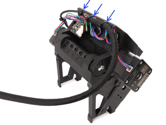
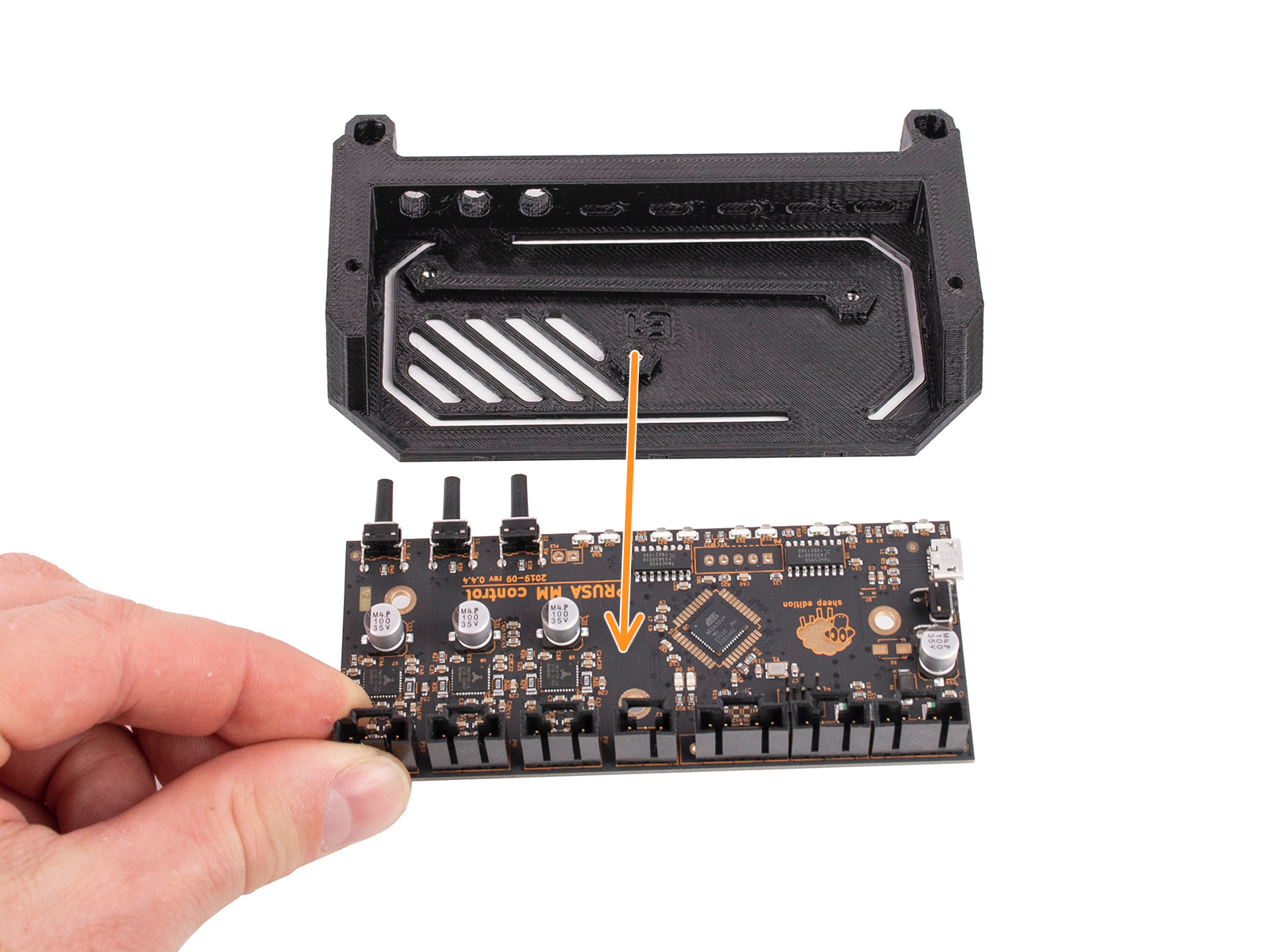
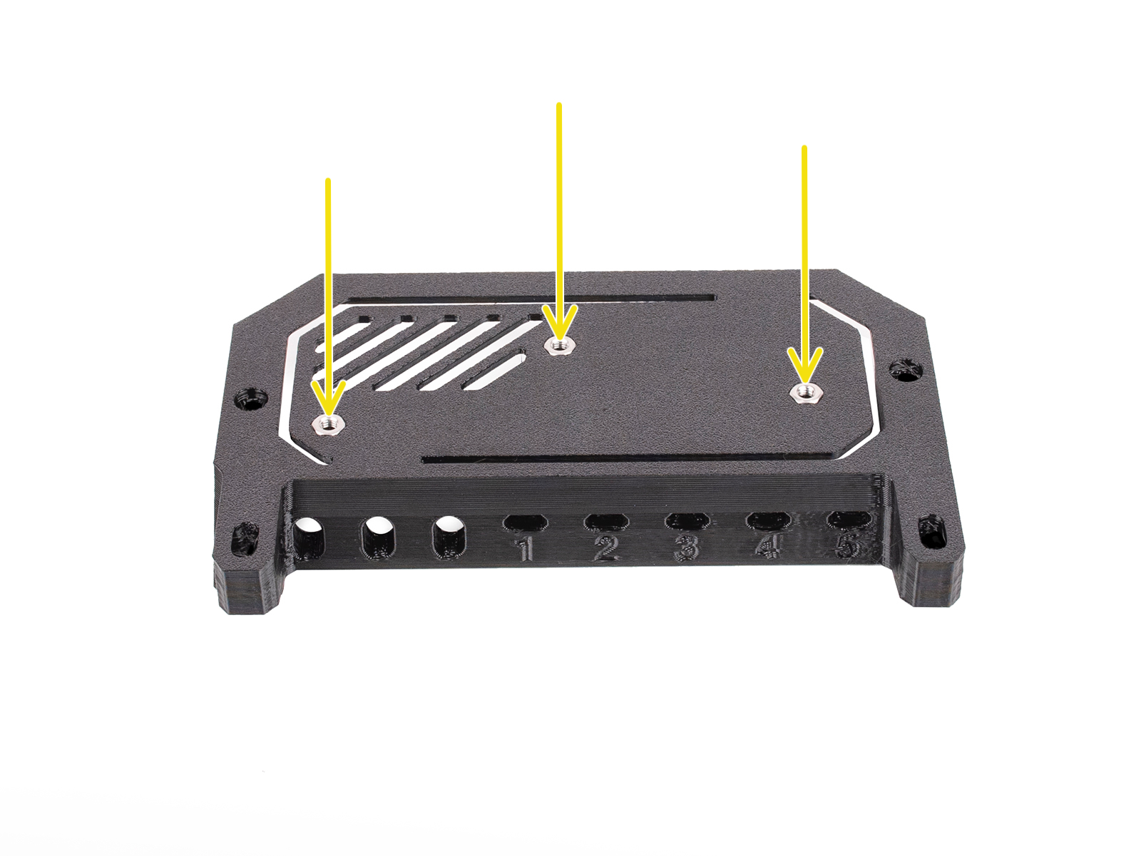
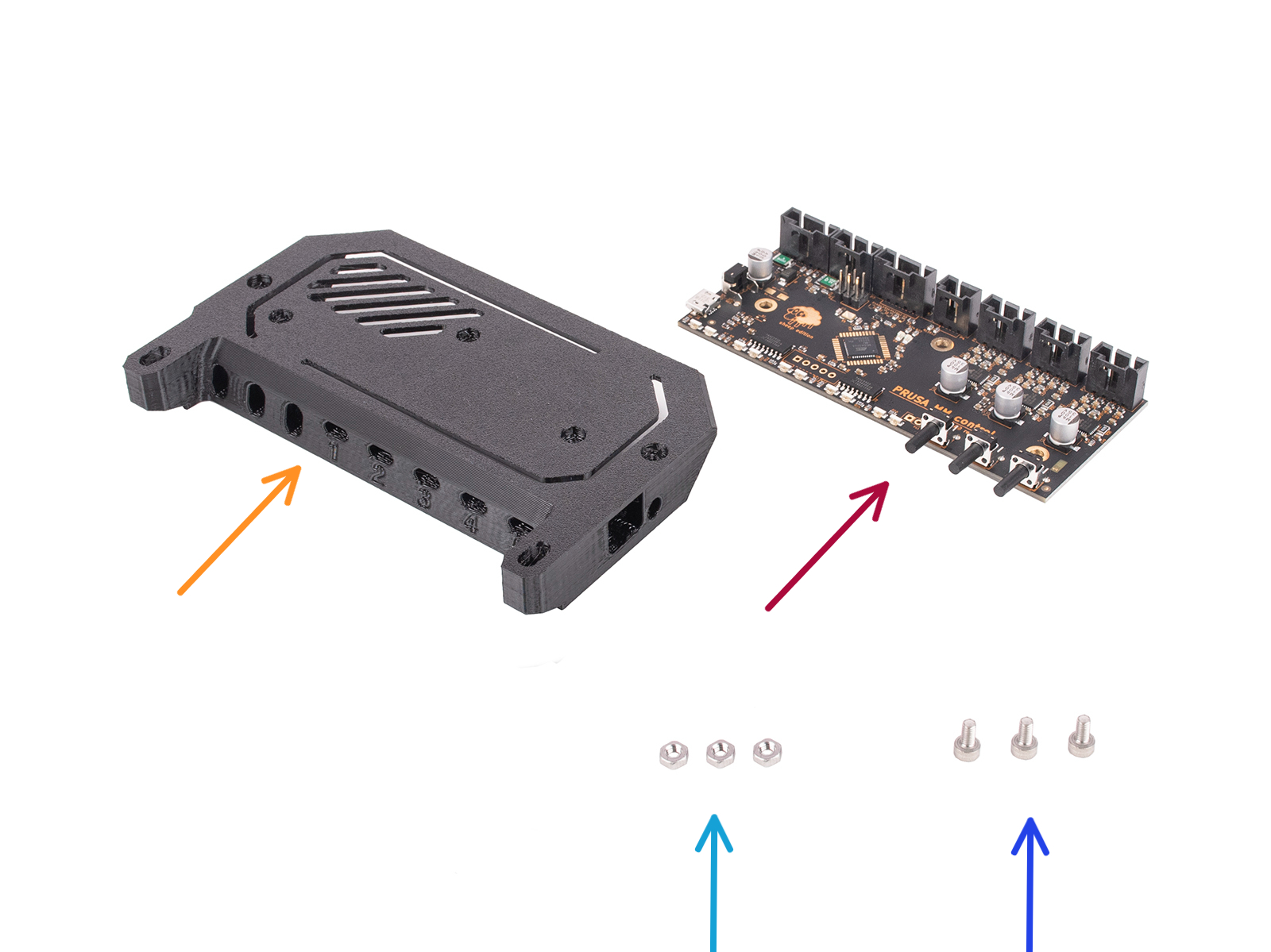
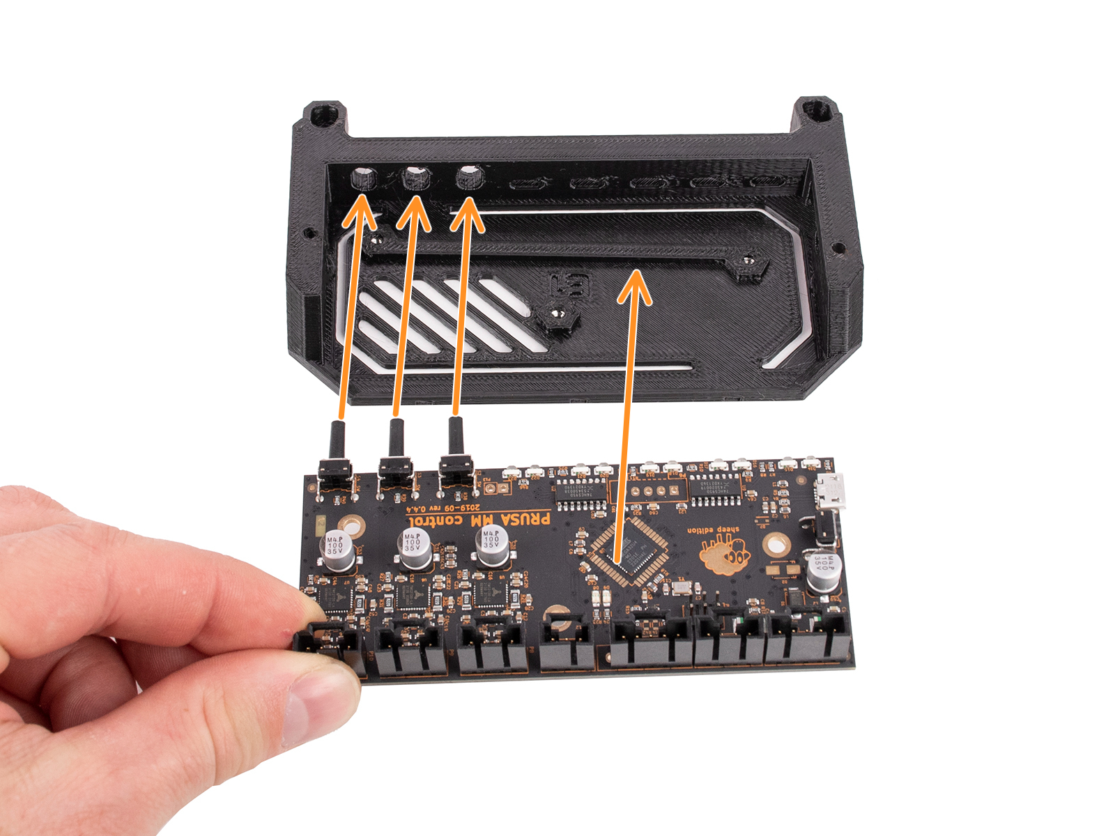
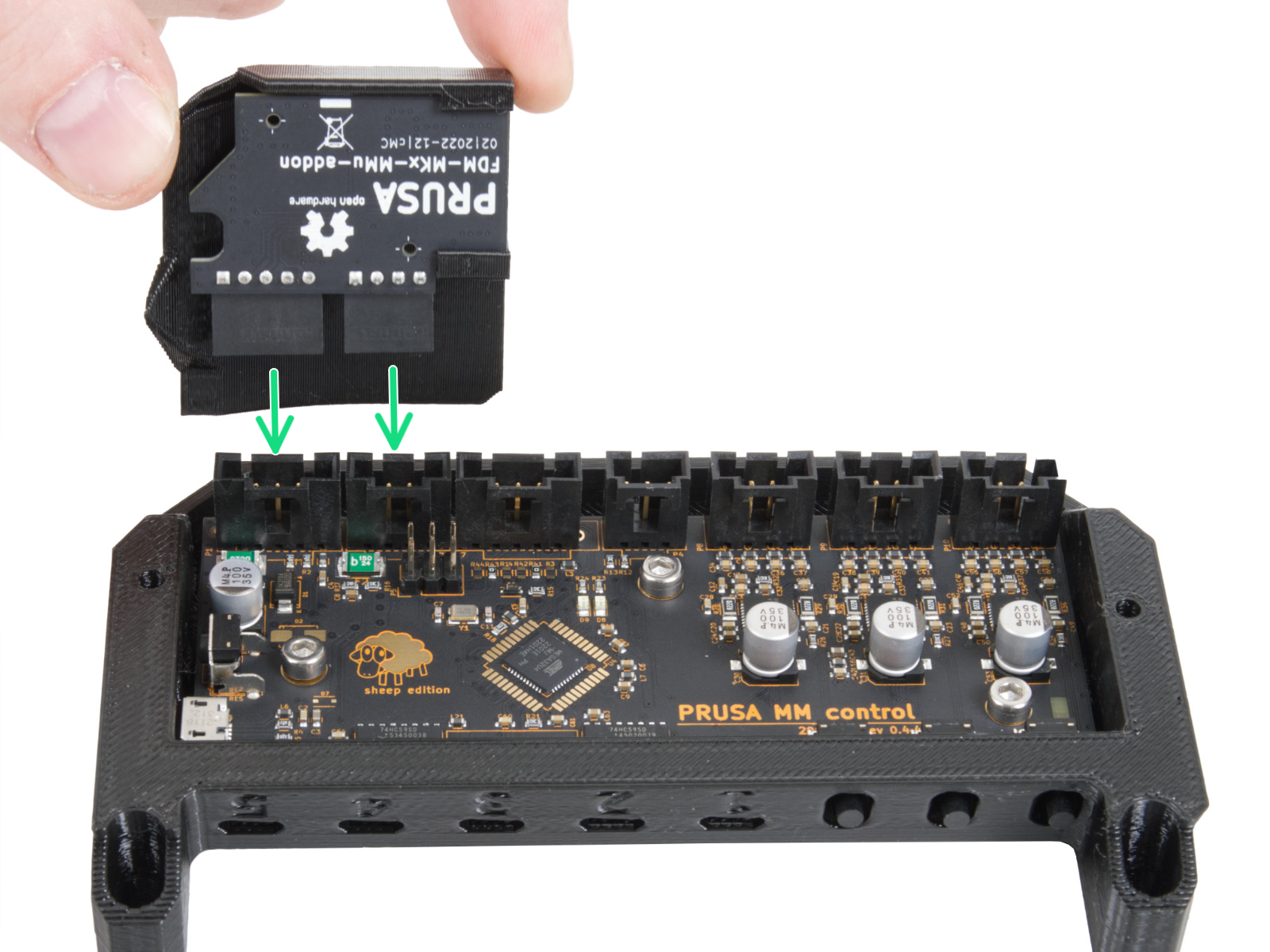
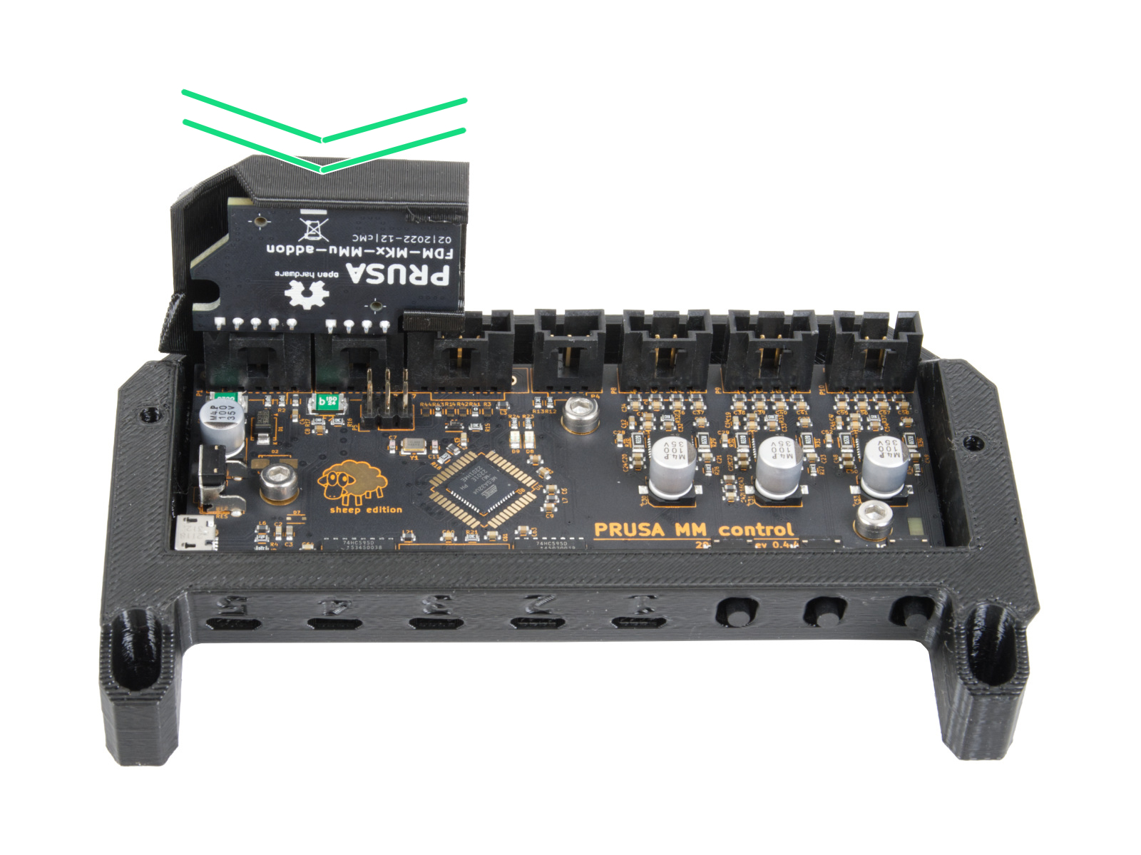
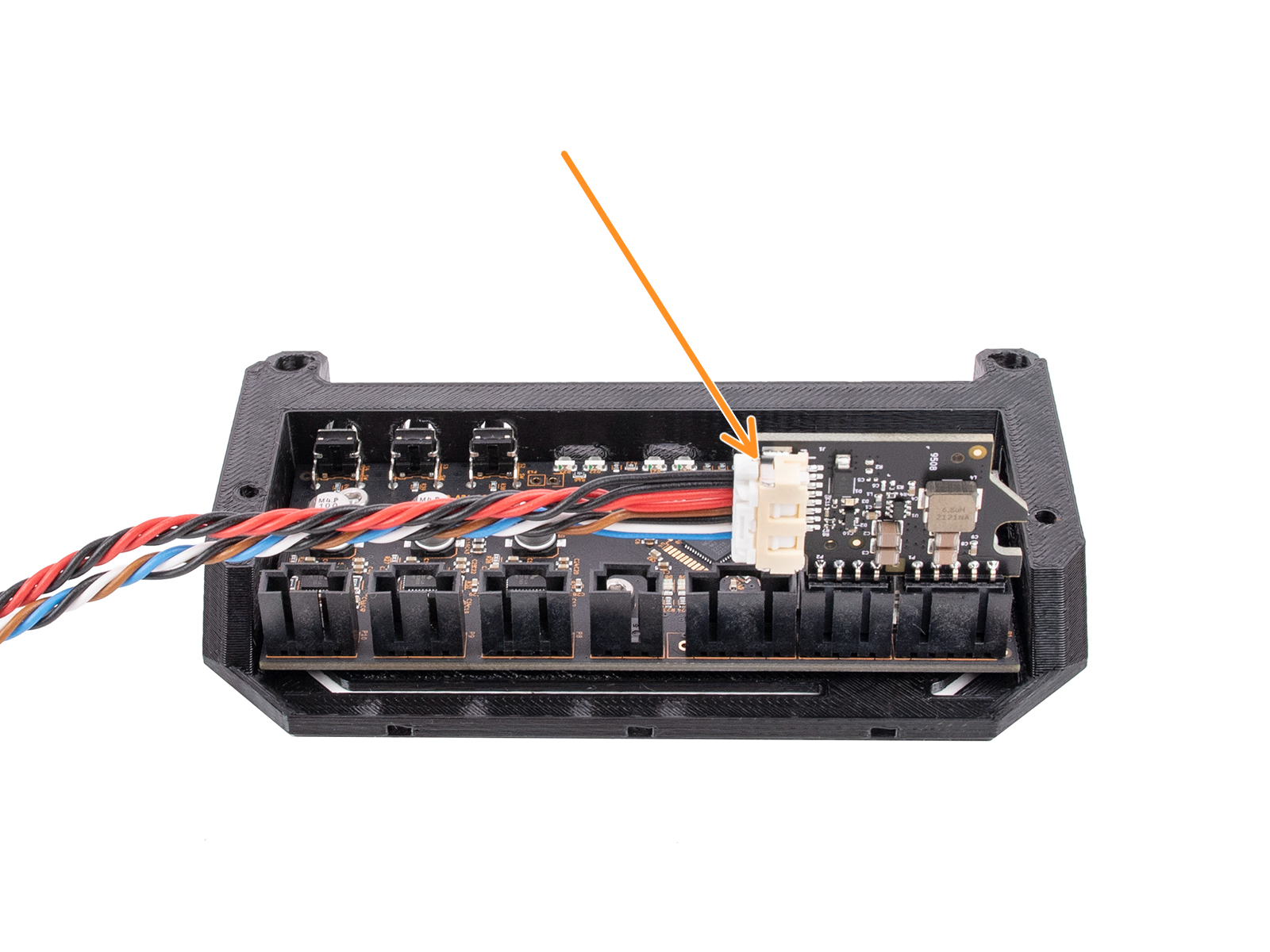
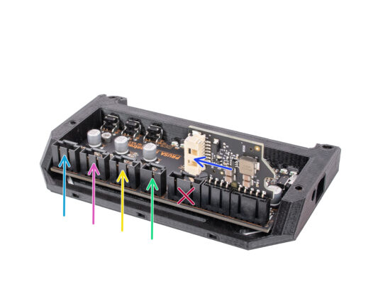
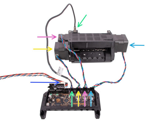
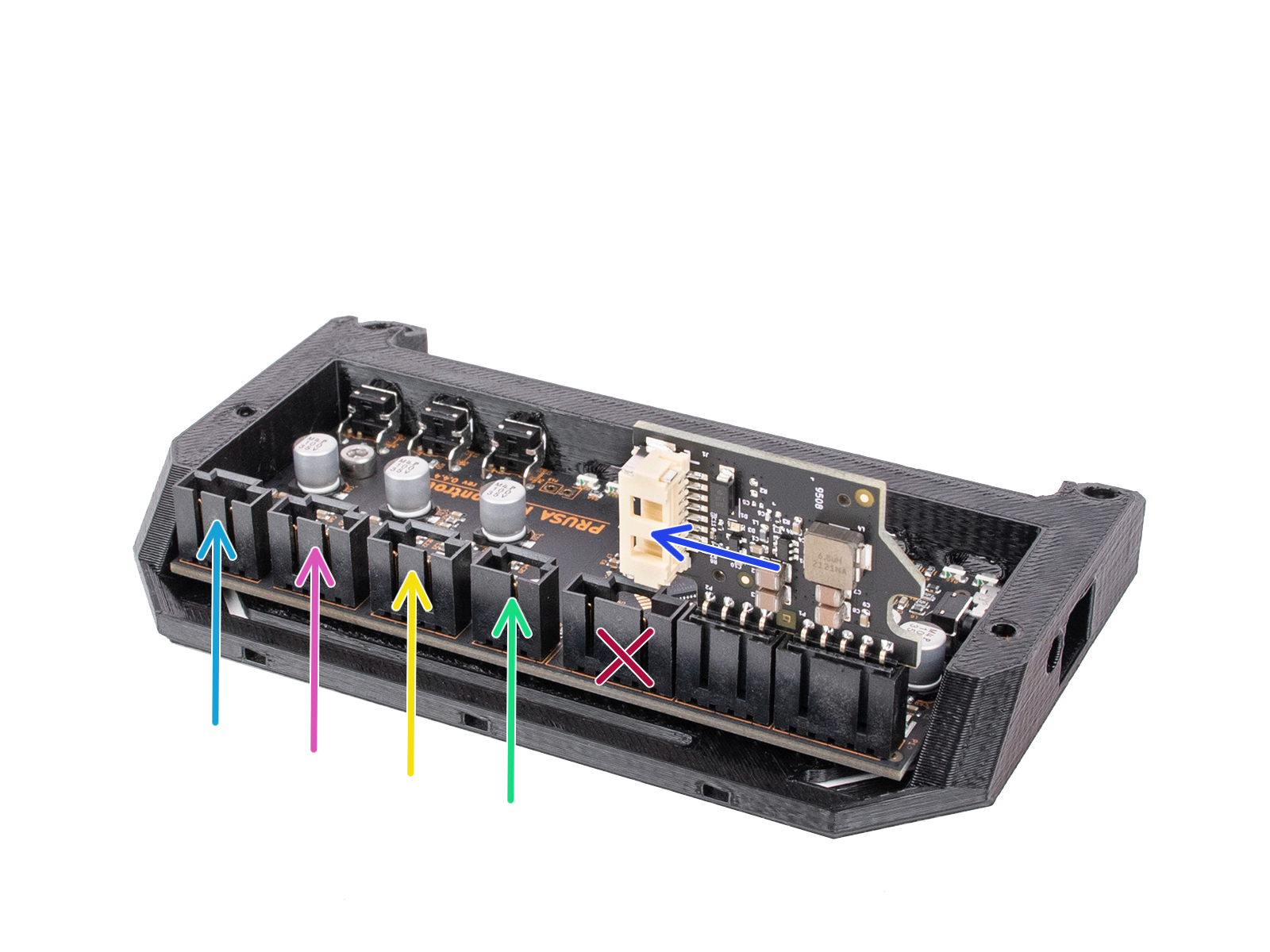
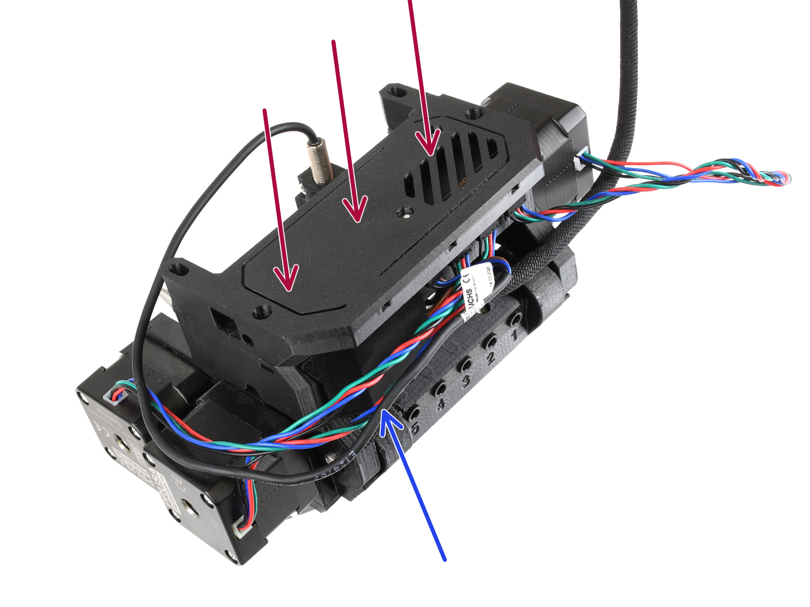
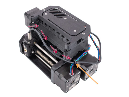
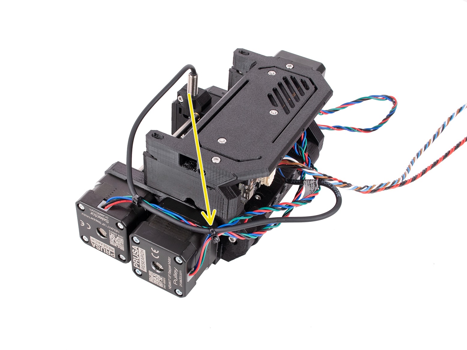
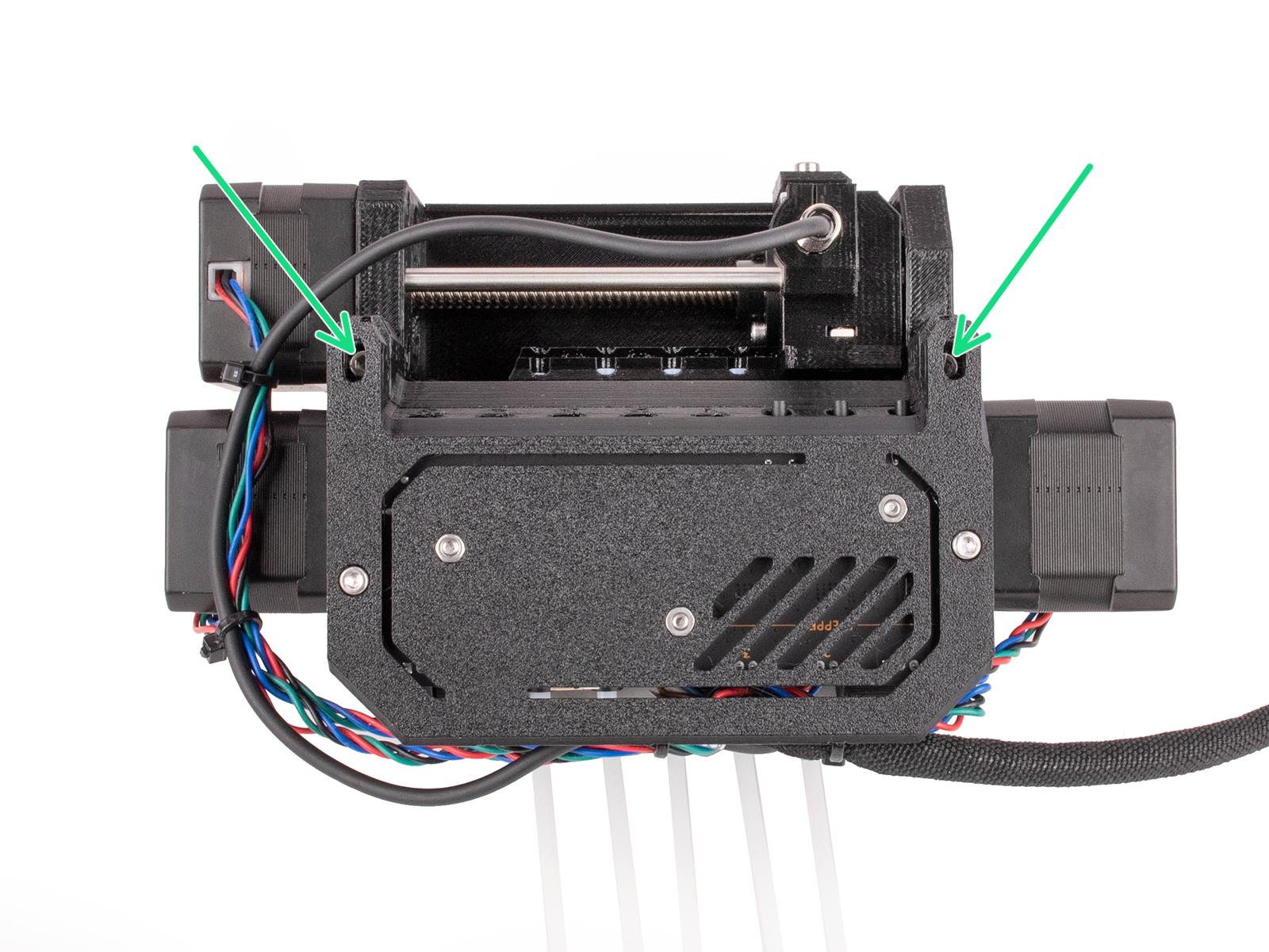
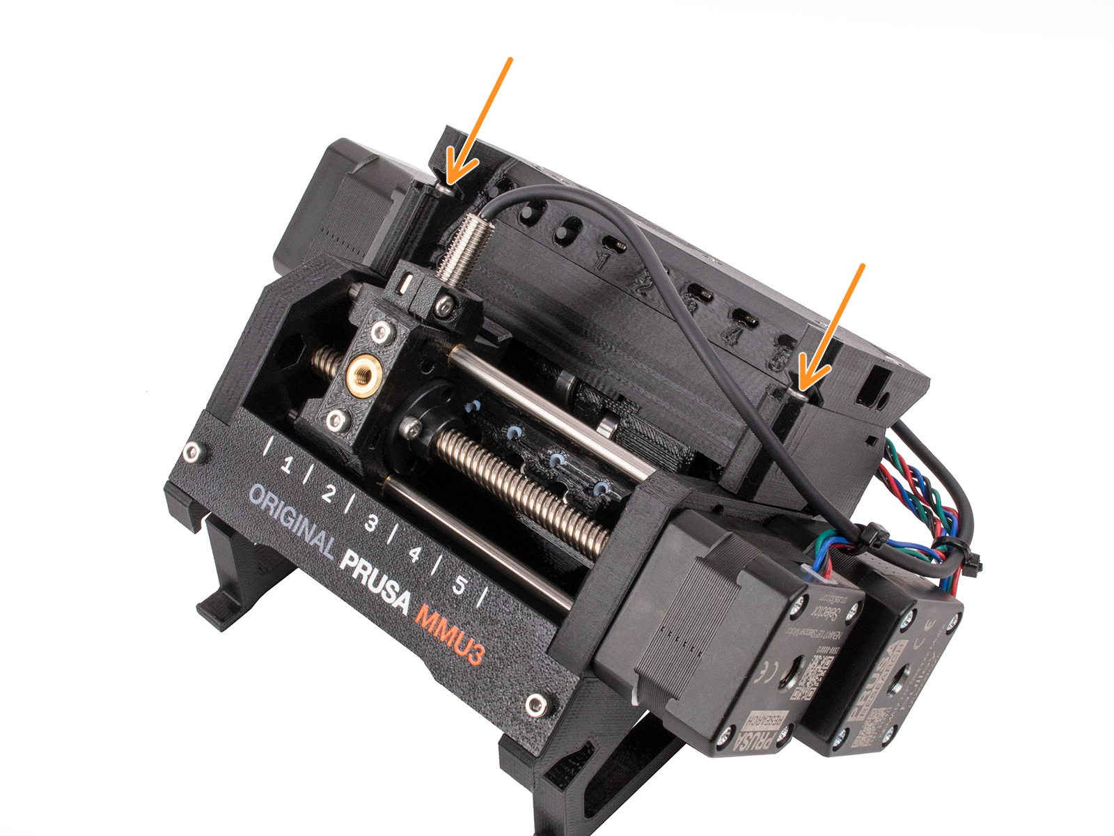
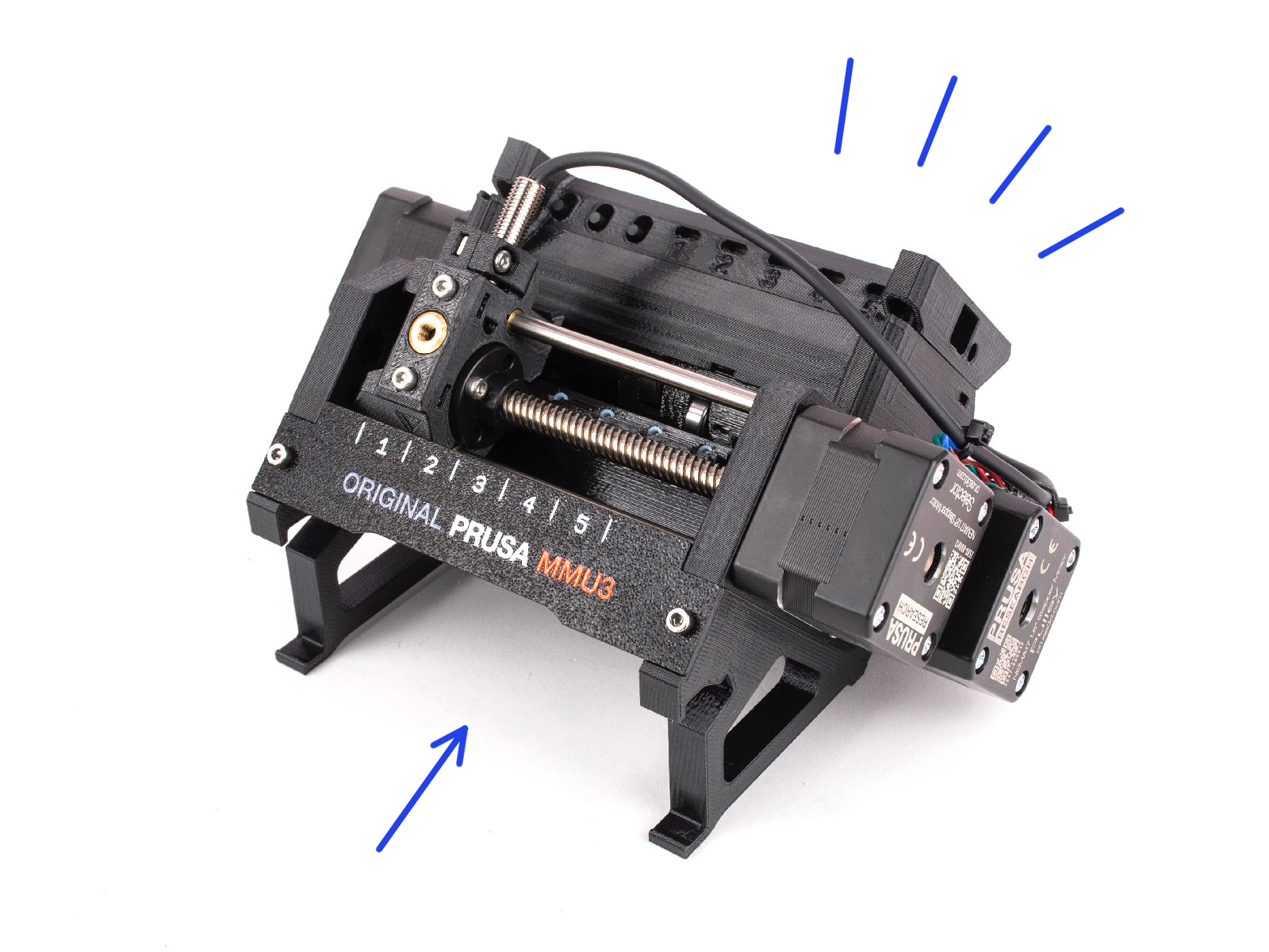
JA
  • English
  • Čeština
  • Español
  • Italiano
  • Deutsch
  • Polski
  • Français
Login

2. MMU3 Unit upgrade

2. MMU3 Unit upgrade
Relevant for:
Last updated 6 days ago
2. MMU3 Unit upgrade
 Difficulty
Moderate
 Steps
17
 Available languages
ENCSPLDEESITFR
Introduction
Introduction
Introduction
Introduction
In this chapter, we will have a look at the ele-cover (the electronics cover) and the electronics wiring.
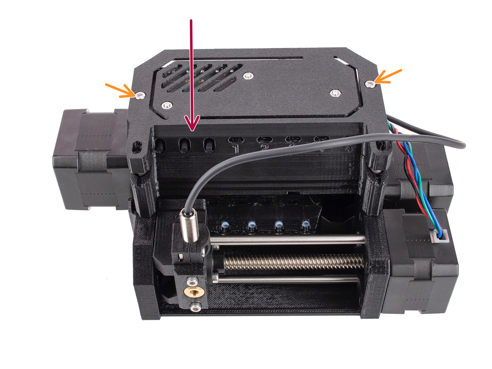
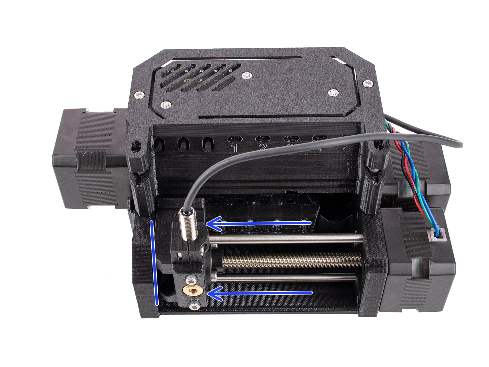
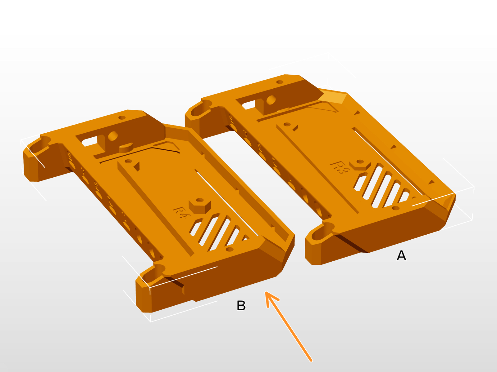
There have been several versions of this part available, which might look slightly different. The version B is slightly taller to comply with ESD regulations.
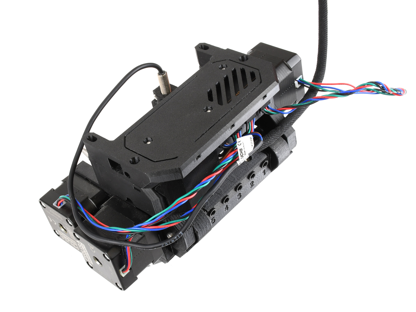
Version B has been included in MMU3 packages shipped after April 2024. If you have this version, skip this chapter.
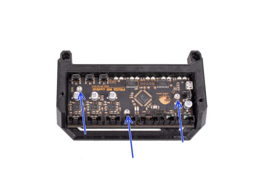
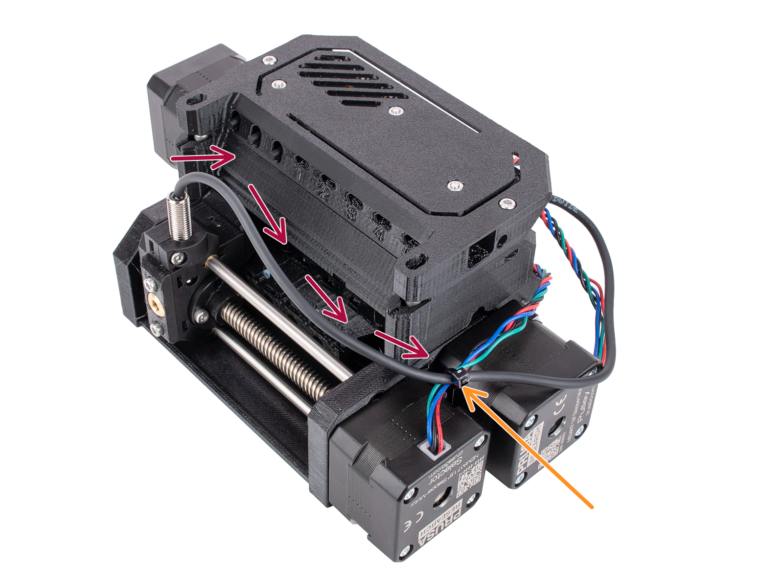
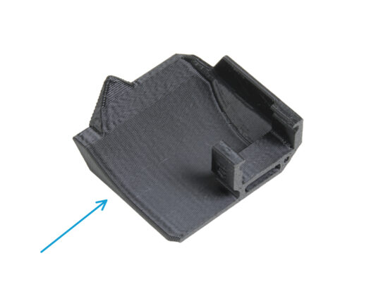
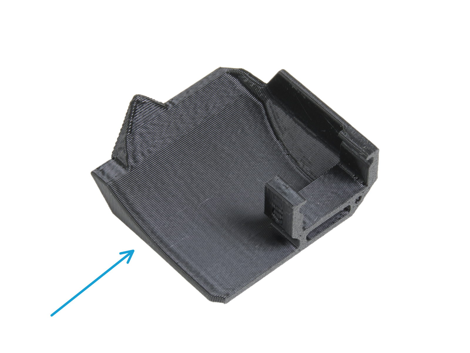
The PD-board-cover component is included with Version B.
If you're adapting an older MMU3 unit to the MK4, it's recommended to replace the ele-cover and add the PD-board-cover.
Preparation
Preparation
Preparation
Carefully cut off all zip-ties holding the cables on the MMU3 unit.
Make sure not to damage any cables.
Remove the two M3x18 screws holding the ele-cover.
Lift the electronics cover.
Disconnecting the cables.
Disconnect all the cables leading to the control board.
Remove the PD-board addon from the control board.
Remove the three M3x6 screws holding the electronics board.
Control board removal
Remove the control board from the ele-cover.
Be careful not to damage any of the small components on the board.
Remove the three M3n nuts from the ele-cover.
Pro tip: use a long M3 bolt partly screwed into the nut. Wiggle it slightly, while pulling the nut out.
Ele-cover parts preparation
For the following steps, please prepare:
Electronics cover (1x)
Make sure you are using the new version B, not the old version A.
MMU Electronics - Control Board (1x) you removed earlier
M3n nut (3x) you removed earlier
M3x6 screw (3x) you removed earlier
Control board assembly
Insert the three M3n nuts into the marked openings on top of the electronics cover. Push them all in until flush with the surface.
Slide in the Control board into the cover. Note the three butons in the front have to go in first.
Fix the board in place with three M3x6 screws.
Be careful not to damage any of the small components on the board.
PD-board parts preparation
For the following steps, please prepare:
MMU / printer cable (1x)
Make sure you are using the correct MK4 version of the cable. See the comparison picture.
M3x18 screw (2x) you removed earlier
PD-board addon (1x) you removed earlier
PD-board-cover (1x)
Installing the PD-board-cover
Slide the PD-board into the brackets on the PD-board-cover. Note the correct orientation of the parts.
Start sliding in at a slight angle.
Plug the PD-board into the leftmost connectors on the electronics board. Gently push down on the PD-board.
PD-board installation
Verify the PD-board occupies the two connectors on the side of the control board
The white connector on the PD-board is pointing inwards.
For easier orientation in the picture, some photos do not include the PD-board cover.

Make sure the PD-board is connected the exact same way as seen in the picture.

If you plug in the PD-board incorrectly, you will damage the electronics. Any damage caused to the printer due to an incorrect electronics assembly is not covered by warranty.

Don't connect or disconnect the cable if the printer is connected to the power outlet or is powered on.
Connect the MMU/printer cable into the PD-board.
Connecting the cables
Prepare the unit and the electronics board assembly as seen in the picture. Follow the cables to plug them in the correct order.
MMU/Printer cable
SuperFINDA sensor cable
Pulley motor cable
Selector motor cable
Idler motor cable
Rule of thumb for the motor cables is; if you look from the back of the unit, the motor connectors are on the same sides as the motors, while the motor at the front (selector) occupies the middle connector.
Electronics assembly

Attach the electronics assembly to the MMU unit.

Make sure the side with the buttons is pointing to the front.

Look at the back to see if the PD-board doesn't interfere with the cables. The cables should be guided over the PD-board, not beneath.
Fix the electronics in place by two M3x18 screws.
Use the correct type of screws. In case you used longer ones, the unit might not work as expected.
ケーブルの整理 (パート 1)
ケーブルの整理 (パート 1)
ケーブルの整理 (パート 1)
ケーブルの整理 (パート 1)
Ensure that the selector is fully moved to the left.
Arrange the SuperFINDA cable so that it joins the motor cables on the side of the unit as seen in the picture.
Leave enough slack in the cable so that it doesn't bend too much with the selector reaching even the first filament position!
Join the Selector motor cable with the SuperFINDA cable using a zip-tie in the marked position, as seen in the picture.
Join the cables together with the Pulley motor cable in the marked position using a zip-tie.
ケーブルの整理 (パート 2)
ケーブルの整理 (パート 2)
ケーブルの整理 (パート 2)
Join the Idler motor cable with the MMU/Printer cable on the right side. Tuck any excess cable length under the electronics cover.
Fix these cables to the marked attaching point on the ele-cover using a zip-tie.
Ensure there is enough slack in the cables so that the zip-tie does not pull by them when tightened.
Leave as much slack as possible in the cable bundle between the motors and the electronics so the unit can be opened up later on without the risk of damaging the cables!
Bundle the loose cables together using a zip tie.
Verify your cable management looks the same as seen in the picture.
Rear PTFE installation
Insert the five long PTFE tubes into the openings with the black collets on the back of the MMU unit.
Undo the two idler tension screws and open up the unit.
There are small windows next to each of the pulley positions. Verify the PTFE tube is fully inserted and its end is visible inside the window. If not, push the tube in some more.
Setting the Idler tension
Close the unit and tighten the idler tension screws slightly.
Adjust both of the idler tension screws so that the top of the screw head is slightly above the top surface of the idler-body.
This is the setting which works for the majority of materials. Some specific filaments might require a slightly different idler tension setting.
The correct idler tension is crucial and might require further adjustment on your MMU unit.
Continue
Continue
Your MMU3 unit is ready to be mounted. But more on that later.
Continue to the following chapter to upgrade your buffer.
Was this guide helpful?

Comments

Still have questions?

Still have questions?

If you have a question about something that isn't covered here, check out our additional resources.
And if that doesn't do the trick, you can send an inquiry to [email protected] or through the button below.

Contact us