Español
Login
Impresoras 3D
Materiales
Piezas y accesorios
Para Empresas
Software
Modelos 3D
Comunidad
Ayuda
Cursos
Blog
Empresa
Soporte
Original Prusa XL
Mantenimiento de la impresora
How to replace trapezoid nuts (XL) | Comenzar el montaje
1. Comenzar el montaje
Paso 1 de 35 (Capítulo 16 de 42)
Contenidos
Comentarios
Dificultad
Moderada
Idiomas disponibles
Comenzar el montaje
Contenidos
Mantenimiento de la impresora
How to replace the CoreXY plastic parts
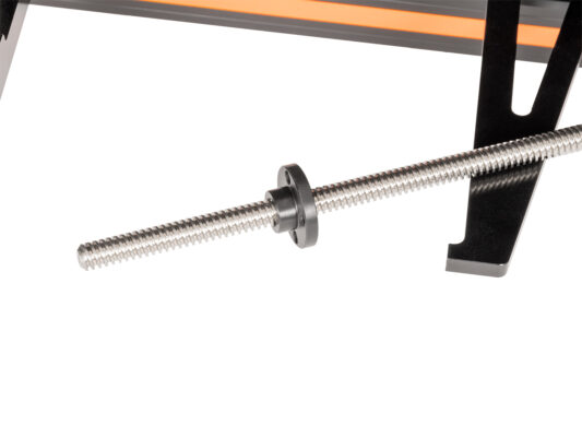
Como reemplazar las tuercas trapezoidales (XL)
Cómo reemplazar un ventilador de impresión (XL multi cabezal)
How to replace the PDU splitter (XL)
Cómo instalalar el Adaptador Nextruder a boquilla V6 (XL monocabezal)
Como reemplazar la boquilla Prusa (XL monocabezal)
Cómo sustituir el conjunto del Hotend (XL monocabezal)
Embalaje de la impresora para devolución - Material de embalaje original (XL)
Cómo sustituir la cubierta del conector del cable principal (XL)
Cómo reemplazar la boquilla Prusa (XL multicabezal)
Cómo sustituir un motor del eje Z (XL)
Embalaje de la XL Multicabezal para devolución - Material de embalaje original
Cómo sustituir un azulejo de la base calefactable y un cable del azulejo (XL)
Cómo reemplazar un ventilador de impresión (XL de un cabezal)
How to fix Modular bed error (HW solution)
Como reemplazar las tuercas trapezoidales (XL)
Comenzar el montaje
Introducción
Herramientas necesarias para este capitulo
Unloading filament
Printer preparing
Spool holder removing
Uninstalling the Wi-Fi antenna
Detaching the filament sensor
Cable cover removing
Preparing the printer: placing the printer
Uncovering the Z motor cable
Releasing the Z motor
CAUTION: Lubricant Handling
Pulling out the Z motor
Quitando la antigua tuerca trapezoidal
Installing the Trapezoid nut: parts preparation
Installing the Trapezoid nut: installing the nut
Installing the Trapezoid nut: Z motor attaching
Securing Z motor: parts preparation
Securing the Z motor
Securing the Trapezoid nut
Securing Bed-frame-mount-fixed
Covering Z motor
Turning the printer
Cable cover attaching: parts preparation
Cable cover attaching
Preparando el sensor de filamento
Colocando el sensor de filamento
Instalando la antena Wi-Fi: preparación de las piezas
Instalando la antena Wi-Fi
Ensamblando el portabobinas: preparación de las piezas
Montaje del portabobinas
Montaje el conjunto del portabobinas
XYZ calibration
Good Job!
Cómo limpiar el sensor de filamento lateral (XL)
Cómo cambiar el xLCD y el cable del xLCD (XL monocabezal)
Cómo reemplazar la placa Dwarf (XL multicabezal)
How to replace Nextruder heatsink (XL Multi-tool)
Cómo reemplazar la placa Dwarf (XL monocabezal)
Cómo sustituir el conjunto del Hotend (XL multicabezal)
Como reemplazar un termistor del fusor (XL monocabezal)
Cómo sustituir una guía lineal del eje Z (XL)
Cómo reemplazar el inserto del perfil (XL)
How to replace the hotend fan (XL Multi-tool)
Cómo reemplazar una fuente de alimentación (XL)
Como reemplazar un calentador del fusor (XL Mono Cabezal)
Cómo lubricar los pasadores de acoplamiento de la Original Prusa XL (MultiCabezal)
How to replace the tch-profile-insert (XL)
Cómo reemplazar la Placa Sandwich (XL)
Cómo reemplazar la goma elástcia en la Original Prusa (XL multicabezal)
Como reemplazar la Cubierta Trasera CoreXY (Original Prusa XL)
Cómo instalalar el Adaptador Nextruder a boquilla V6 (XL Multi Cabezal)
How to replace a XY motor (XL)
Packing the XL Enclosure for return - Original Packing material
How to change the belt (XL)
How to change the xLCD (XL)
How to lubricate linear bearing rails (XL)
How to set up a Buddy3D Cam
How to replace Nextruder heatsink (XL Single-tool)
Como reemplazar un Nextruder (XL de un cabezal)
Comentarios
Inicia sesión
para publicar un comentario
Sin comentarios