ES
  • English
  • Čeština
  • Italiano
  • Deutsch
  • Polski
  • Français
Iniciar sesión

How to replace a PSU (XL)

Menu

How to replace a PSU (XL)

How to replace a PSU (XL)
Relevante para :
Ultima actualización 8 months ago
How to replace a PSU (XL)
 Dificultad
Moderada
 Pasos
24
 Idiomas disponibles
ENCSPLDEITFR
Introduction
Introduction
This guide will take you through the replacement of one of the Power Supply Units (PSU) on your Original Prusa XL.
Las siguientes instrucciones son compatibles con todas los versiones de las Original Prusa XL.
Necessary tools
Necessary tools
Para los siguientes pasos, por favor prepara:
TX10 Torx screwdriver
2.5mm Allen key
3.0mm Allen key
Philips screwdriver
Printer preparation
Printer preparation
Printer preparation
From the rear side, turn the power switch OFF (symbol "O").
Unplug the power cable.
Do not manipulate the PDU and its bolts under any circumstances!
Leave the printer off and disconnected from the mains for at least 10 minutes before proceeding to the next step.
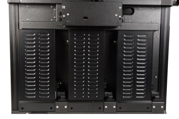
Removing the middle-rear-panel
Using a TX 10 screwdriver, loosen 4x M3x5rT screws. Do not throw them away, we'll use them later.
Remove the middle-rear-panel, gently pull it out.
Disassembling the switch cover
Locate the switch cover on the right side of the PSU that will be replaced.
Using the 2.5mm Allen key, remove the M3x8 screw, and take out the switch cover.
Do not throw the screw away! We'll use it later.
Removing the PSU cover
Using a 2.5mm Allen key, loosen two M3x10 screws that hold the PSU cover. Do not throw them away, we'll use them later.
Carefully slide out the cover. You can use the 2.5mm Allen key or the T10 screwdriver as a lever.
Removing PSU cables (left)
Follow this step in case the PSU to replace is the leftmost one.
Disconnect the following cables:
Two pairs of power cables. Use the Philips screwdriver to loosen them.
Do not throw away the screws and washers, we'll use them later.
PE cable. Use the Philips screwdriver to loosen it.
Leave the screw and washer attached to the PE cable connector.
Power panic
The power panic connector has a safety latch. It is necessary to press the latch before disconnecting. Otherwise, the connector may get damaged.
Removing PSU cables (middle)
Follow this step if the PSU to replace is the central one.
Using the Philips screwdriver, loosen the pair of power cables at the center.
Do not throw away the screws and washers, we'll use them later.
Removing PSU cables (right)
Follow this step if the PSU to replace is the rightmost one.
Using the Philips screwdriver, loosen the pair of power cables at the center.
Do not throw away the screws and washers, we'll use them later.
Removing PSU from frame
Using a 2.5mm Allen key, loosen the M3x16 from the PSU-upper-cover-mount. Start holding the PSU while doing this, with the other hand.
Using a 2.5mm Allen key, loosen slightly, without removing them, the M3x8 screws on the 'bottom mount' of PSU.
With one hand slide the down-angled-ac-adapter upwards, and with the other hand slide up the PSU.
Remove the PSU together with the down-angled-ac-adapter from the frame, then detach the down-angled-ac-adapter.
Do not throw the adapter away, we'll use it later.
Replacing the PSU - parts preparation
Para los siguientes pasos, por favor prepara:
PSU (1x)
M3x6 screws (2x)
M3x20rT screw (1x)
M4x12 screw (1x)
PSU-upper-cover-mount (1x)
Down-angled-ac-adapter (1x)
PSU covers - parts preparation
Del kit de actualización, por favor prepara:
Switch cover (1x)
M3x8 screw (1x)
PSU cover (1x)
M3x10 screw (2x)
Preparing the PSU
Preparing the PSU
Preparing the PSU
Using a Phillips screwdriver, release the terminal screws, without removing them.
Release the center two terminal screws if you are replacing the central or the right PSU.
Release all of the four terminal screws if you are replacing the left PSU.
From the side of the PSU, insert the Down-angled-ac-adapter.
Turn the PSU power switch ON (symbol "I").
Assembling the PSU upper-cover-mount
Inserta un tornillo M4x12 en la PSU-upper-cover-mount.
Locate the hole on the top left side of the PSU.
Coloca la PSU-upper-mount-cover a la fuente de alimentación y fija el tornillo M4x12 con una llave Allen de 3 mm.
Securing the PSU to the frame
En el lado izquierdo de la fuente de alimentación, inserta el tornillo M3x20rT en el PSU-upper-cover-mount y fija la cubierta con la placa posterior de la impresora.
En la parte inferior de la fuente, aprieta dos tornillos M3x6 con la llave de 2.5 mm.
Empujando hacia abajo el Down-angled-ac-adapter, asegura su posición.
Connecting the left PSU cables (CRITICAL) - part 1
WARNING: Triple-check you have connected the cables correctly. There is a risk of damaging the PSU or the printer itself, if the cables are connected incorrectly or not tightened properly!
Starting from the left, the PSU polarity is: ++--
Make sure the bent part of the cable connector is always facing up, and connected under the square washer.
One cable pair is labeled with B.
Connect the red cable on the leftmost connector.
Connect the black cable on the rightmost connector.
The other cable pair does not have a label.
Connect the red cable on the center-left connector.
Connect the black cable on the center-right connector.
We will connect the remaining cables on the next step.
Connecting the left PSU cables (CRITICAL) - part 2
WARNING: Triple-check you have connected the cables correctly. There is a risk of damaging the PSU or the printer itself, if the cables are connected incorrectly or not tightened properly!
Starting from the left, the PSU polarity is: ++--
Plug the power panic cable on its connector.
Using the Philips screwdriver, fully tighten the bolt with the washer under it to connect the PE cable.
Double-check now the correctness of the connection for the two pairs of power cables.
Triple-check again that all screw-attached connectors are correctly connected, as tight as possible, and with the correct polarity.
Connecting the center PSU cables (CRITICAL)
WARNING: Triple-check you have connected the cables correctly. There is a risk of damaging the PSU or the printer itself, if the cables are connected incorrectly or not tightened properly!
Starting from the left, the PSU polarity is: ++--
Make sure the bent part of the cable connector is always facing up, and connected under the square washer.
The cable pair does not have a label.
Connect the red cable on the center-left connector.
Connect the black cable on the center-right connector.
Triple-check again that all screw-attached connectors are correctly connected, as tight as possible, and with the correct polarity.
Connecting the right PSU cables (CRITICAL)
WARNING: Triple-check you have connected the cables correctly. There is a risk of damaging the PSU or the printer itself, if the cables are connected incorrectly or not tightened properly!
Starting from the left, the PSU polarity is: ++--
Make sure the bent part of the cable connector is always facing up, and connected under the square washer.
The cable pair is labelel A.
Connect the red cable on the center-left connector.
Connect the black cable on the center-right connector.
Triple-check again that all screw-attached connectors are correctly connected, as tight as possible, and with the correct polarity.
Assembling the switch cover
Inserta el tornillo M3x8 en la switch-cover.
En el lado derecho de la fuente de alimentación, localiza el orificio de la placa posterior de la impresora.
Con una llave Allen de 2.5 mm, fija el tornillo de la tapa con la parte posterior de la impresora.
Assembling the PSU cover
Inserta los dos tornillos M3x10 en la tapa de la fuente de alimentación.
Inserta la cubierta de la fuente preparada debajo de la fuente.
Aprieta ambos tornillos M3x10 con una llave Allen de 2.5 mm.
Testing the printer
Testing the printer
Desde la parte posterior, enchufa el cable de alimentación.
Enciende el interruptor (símbolo "I").
Perform a selftest or test the printer heating as a test for the replaced PSU.
Good job!
Good job!
That's it, good job! You successfully replaced the PSU on your Original Prusa XL.
¿Fue útil esta guía?

Comentarios

¿Todavía tienes preguntas?

¿Todavía tienes preguntas?

Si tienes alguna pregunta sobre algo que no se ha tratado aquí, comprueba nuestros recursos adicionales.
Y si eso no lo soluciona, puedes enviar una petición a [email protected] o mediante el botón que hay más abajo.

Contacta con nosotros