EN
  • Deutsch
  • Polski
  • Français
Login
Menu

6A. Hinged Lid with MMU3

6A. Hinged Lid with MMU3
Relevant for:
Last updated 15 hours ago
6A. Hinged Lid with MMU3
 Difficulty
Difficult
 Steps
47
 Available languages
PLDEFR
Introduction
Introduction
Introduction
Introduction
This chapter guides you through the installation of the MMU3 into the Enclosure.
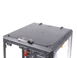
The MMU3 can only be installed after the Hinged Lid is in place.

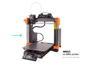
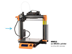
Since the MMU3 is compatible with multiple printer models, note that some parts of your printer may slightly differ from the pictures. However, the assembly process remains the same.

Printable parts
Printable parts
If you didn't receive the printable parts in your package, you can download them from Printables.com and print them.
However, to complete the installation, you'll also need to obtain a package of additional hardware, including screws, nuts, long PTFE tubes, and magnets.
These components should be included in the Printer + Enclosure + MMU3 Bundle.
LCD Removal
LCD Removal
LCD Removal
LCD Removal
If you have the LCD mounted on the enclosure, follow these steps:
From the inside, remove the two screws holding the LCD
Disconnect the LCD cable / cables.
On MK4/S, disconnect also the grounding connector.
Move the cable bundle to the inside of the enclosure.
Spool Holder Removal
Remove the two screws on the right side of the Enclosure, holding the spool holder.
Remove the spool holder.
Filament Guide Removal
Press down the collet on the filament fitting on the extruder.
While keeping the collet pressed, pull the PTFE tube out of the fitting.
Cut the zip tie securing the PTFE tube on the inner side of the top front profile.
Remove the two screws securing the filament guide and take it out of the enclosure.
PSU Removal
PSU Removal
PSU Removal
PSU Removal
Place the printer at an angle (as shown) inside the enclosure, positioning it behind the anti-slip dampers.
Unlock all PSU locks, then grasp the handle and remove the PSU assembly from the back panel.
Place the PSU on the heatbed, protected by a cloth, with the PSU handle facing upwards.
Printer Removal
Printer Removal
Open the top lid.
Grasp the printer by its frame and carefully lift it out of the enclosure.
Avoid scratching the printer and enclosure.
MMU3 Installation
MMU3 Installation
If you are installing a new MMU3 unit onto the printer:
If necessary, re-connect the LCD to the printer so that it’s functional again.
Continue to the MMU3 Assembly guide
Once you've installed the MMU3 unit on the printer, test it. Afterward, return to this guide and proceed with the next step.
If you have temporarily disconnected the MMU3 unit from the printer during the enclosure assembly, continue to the next step.
Buffer Removal
Buffer Removal
Disconnect ALL PTFE tubes from the buffer.
Move the buffer away from the printer.
In the following steps, we will prepare the Enclosure and modify the Buffer before installing them into the Enclosure.
Spool Holders: Parts preparation
For the following steps, please prepare:
mmu_enclosure_spoolholder (5x)
mmu_enclosure_spoolholder_R3_cap (5x)
M3x20 screw (5x)
M3x12 screw (10x)
M3x10 screw (5x)
M3nN nut (10x)
Spool Holders Preparation 1
Take one spool holder. Add the Cap part onto the small tubular part of the spool holder.
Insert the M3x20 screw through the tubular part and tighten it against the Cap. Ensure it’s tight enough to hold the Cap in place, but still allows it to rotate.
Pro tip: If it’s hard to turn, you can use one of the other spool holders as a handle for the cap part.
Do not tighten the M3x20 screw fully. The cap must be able to rotate freely.
Spool Holders Preparation 2
Add the M3x10 screw onto the end of the Cap. Just start the thread. Do not tighten it up yet!
Install the two M3nN nuts into the openings on the Spool holder. Push them all the way in.
Repeat the same process until you assemble all five spool holders.
Spool Holders Installation 1
Now, let's move on to the right side of the enclosure.
Run two M3x12 screws through the marked openings, from the inside to the outside.
Mount the first spool holder onto the screws. Tighten the screws fully.
Spool Holders Installation 2
Using two M3x12 screws, attach a second spool holder into the bottom front corner.
Using the same technique, mount the remaining three spool holders onto the LEFT side of the enclosure in the marked positions.
Verify that the spool holders are positioned as shown in the picture.
Internal Lock Preparation
Insert the M3x12 screw through the Lock B part.
Orient Lock B with the screw pointing upwards and the small recess on the left.
Orient Lock A so that the circular opening is on the left.
The recessed circular part must be pointing up.
Fit the two parts together, ensuring they align properly.
Internal Lock Installation
Open the top lid and remove the screw on the inside that secures the handle.
Orient the lock so that the small protruding part aligns with the opening in the sheet metal.
The screw fits in the place of the one you removed earlier.
Fix the lock in place by tightening the M3x12 screw.
PTFE Side Holder Installation 1
On the left side of the enclosure, remove the marked nylon rivet.
From inside the enclosure, push the center pin of the rivet, then pull the entire rivet out from the outside.
Run two M3x8 screws through the marked openings from the inside of the enclosure to the outside.
Attach the PTFE Side Holder onto the screws.
Make sure the lifted part of the holder is pointing towards the front of the Enclosure!
Tighten the screws to fix the holder in place.
PTFE Side Holder Installation 2
On the right side of the enclosure, remove the marked nylon rivet.
Using the two M3x8 screws, fix the other PTFE Side Holder in place.
Make sure the lifted part of the holder is pointing towards the front of the Enclosure!
Covers Removal
Covers Removal
On top of the Enclosure, remove the marked two covers.
Push the center part of the rivets holding the covers from the bottom, then remove the rivets from the top along with the covers.
Buffer Mount: parts preparation
For the following steps, please prepare:
Buffer mount (1x)
M3x6 screw (3x)
M3nN nut (2x)
M3n nut black (1x)
PTFE top passthrough (1x)
Buffer Mount Installation
Insert two M3nN nuts into the marked openings on the Buffer Mount.
Place the Buffer Mount on top of the enclosure.
Ensure the part of the mount with the nuts is oriented toward the front of the enclosure.
Attach the mount to the top lid using two M3x6 screws from the bottom.
PTFE Passthrough Installation
Insert the M3n black nut into the PTFE passthrough part.
Attach the passthrough part onto the back of the top lid.
Secure it in place by inserting the M3x6 screw from the bottom of the lid and tightening it.
Buffer Preparation 1
Take the Buffer itself.
Remove all five cassette cartridges from the buffer.
Remove the M3x30 screw holding the Buffer Leg.
Remove the Buffer Leg.
Reinsert the two M3x30 screws. Tighten them lightly to avoid bending the Buffer.
Buffer Preparation 2
Remove the M3x30 screw holding the printer holder.
Remove the countersunk M3x30 screw on the opposite side that secures the printer holder.
Remove the printer holder part.
Enclosure Buffer: parts preparation
For the following steps, please prepare:
Buffer Side L (1x)
Buffer Side R (1x)
Buffer Plate Holder L (1x)
Buffer Plate Holder R (1x)
Magnet 2x5x20 (11x)
The magnets are strong but brittle. After separating them, keep them a sufficient distance apart to prevent them from shattering.
Magnets Installation
Install four magnets into the marked openings on the Buffer Side L part.
Install three magnets into the marked openings on the Buffer Side R part.
Install two magnets into the Plate Holder L, and the last two magnets into the Plate Holder R parts.
Enclosure Buffer Assembly 1
Orient the Buffer as shown in the picture: laying flat with the opening for the cassette segments on the left side.
Remove the Plate holder part from the former bottom of the buffer.
Use needle-nose pliers if the plate holder is difficult to remove.
Install the Buffer Side R (the part with three magnets) onto the Buffer, ensuring the magnets are pointing downwards.
Ensure all the plates are fully engaged into the Side R part.
Enclosure Buffer Assembly 2
Remove the two marked plate holders on the opposite side.
Install the Buffer Side L part (with four magnets) onto the Buffer.
Ensure the magnets are oriented the same way as on the opposite side.
Enclosure Buffer Assembly 3
Remove the two Plate Holders.
Install the Plate Holder L onto the Buffer, on the side with the four magnets.
Ensure the magnets are oriented to the same side as the other parts.
Install the Plate Holder R onto the Buffer, on the side with the three magnets. Ensure the magnets are oriented to the same side as the other parts.
Enclosure Buffer Installation
Insert all five cassettes back into the buffer.

Mount the buffer onto the top lid of the enclosure. The part with the cassettes should hook into the plastic part on the top lid.

The front part of the buffer should hold securely in place due to the magnets.
The enclosure is now ready for the printer installation in the upcoming steps.
Printer Preparation
Printer Preparation
Printer Preparation
Printer Preparation
Before you place the printer in the enclosure, prepare the printer in this state:
PSU is removed from the frame and placed on the protected heatbed
The printer frame support is installed on the printer.
If you plan to use the externally mounted LCD, you can disconnect and remove it from the printer.
Printer Installation
Grasp the printer by its frame and carefully insert it into the enclosure at a slight diagonal angle to prevent scratching both the printer and the enclosure.
Ensure the printer is not placed on any cables or PTFE tubes!
Place the printer at an angle, as shown in the picture, inside the enclosure, positioning it behind the anti-slip dampers.
This is just a temporary position for the printer. We'll adjust it to the correct position later.
PSU Installation
PSU Installation
PSU Installation
PSU Installation
From inside the enclosure, grasp the PSU by its handle.
It's more convenient to use your right hand for this task.
Insert the PSU through the opening at the bottom of the back panel, starting with the PSU retainer (the part with the magnets).

Tilt the PSU towards the back panel, ensuring the PSU remains outside the enclosure while the PSU holder is inside the enclosure.

Ensure the PSU holder fits perfectly onto all four PSU locks.
Turn all PSU locks 90° to secure the PSU assembly.
Printer Positioning
Printer Positioning
Printer Positioning
Printer Positioning
Rearrange the printer as shown in the picture. Center it in the enclosure and adjust it to the correct position.
Ensure the two rear anti-slip dampers are locked against the rear plate from the inside.
The two front anti-slip dampers must be secured against the front plate from the outside.
Guide the LCD cable bundle under the printer, from the electronics to the front of the enclosure. Leave the cable loose for now.
LCD Installation: parts preparation
If you're using the externally mounted LCD, proceed with these steps. If not, skip them.
For the following steps, please prepare:
LCD assembly (1x) compatible with your printer
M3x8 screw (2x) you removed earlier
LCD Connection
LCD Connection
LCD Connection
LCD Connection
Guide the LCD cable bundle through the cutout in the bottom panel.
Place the LCD assembly next to the enclosure, ensuring the holders are pointing away from the enclosure, as shown in the picture.
MK4/S: Connect the xLCD cable to the xLCD board, ensuring the safety latch is properly engaged on the side of the slot marked with the orange triangle on the board.
MK4/S: Connect the grounding Faston connector onto the xLCD
MK3S+: Connect the cable marked with two stripes into the left slot (EXP2)
MK3S+: Connect the cable marked with one stripe into the right slot (EXP1)
LCD Installation
LCD Installation
LCD Installation
LCD Installation
Move the LCD assembly towards the enclosure, as seen in the picture.
Fix it to the metal profile using two M3x8 screws. Tighten the screws fully.

Secure the LCD cable bundle to the bottom of the enclosure. Guide a zip-tie through the perforation and tighten it around the cable bundle.

PTFE Tube Installation 1
Guide the PTFE tubes from the MMU unit through the opening at the rear of the top lid  of the Enclosure.
Connect the PTFE tubes to their corresponding numbered cassettes in the Buffer.
Insert two 4x2.5x1100 PTFE tubes into cassette positions 4 and 5.
PTFE Tube Installation 2
Insert the two PTFE tubes into the side holder.
Guide the PTFE tubes towards the spool holders on the right side of the Enclosure (when looking from the front side)
Push the ends of the PTFE tubes through the cap on each spool holder. The end should be just behind the cap.
The end of the tube should be positioned just behind the cap.
If the PTFE tube is difficult to insert, slightly loosen the M3x10 screw.
PTFE Tube Installation 3
Slightly tighten the M3x10 screw on the cap to secure the PTFE tube in place, being careful not to overtighten.
Tighten the screw very lightly just so that the PTFE tube holds in place. Do not overtighten, as this could cause filament drag and affect the proper function of the MMU.
On the back of the printer, approximately in the middle of the long PTFE tubes...
Join the tubes together using the corresponding two-way clip.
PTFE Tube Installation 4
Insert three PTFE tubes into cassette positions 1, 2, and 3.
Guide the tubes through the side holder on the opposite side.
Attach the ends of the tubes to the caps on each spool holder. Secure them in place by gently tightening the M3x10 screws.
Join the tubes together using the corresponding three-way clip.
Loading the Filaments
To load the filaments, first attach the spools onto the spool holders on the side.
Push the filament through the PTFE tube into the buffer, then use the Preload function to load it into the MMU3.
Repeat the process to load the remaining filaments.
Done
Done
Congratulations!
You can now start using your MMU3 inside the enclosure.
Was this guide helpful?

Comments

Still have questions?

Still have questions?

If you have a question about something that isn't covered here, check out our additional resources.
And if that doesn't do the trick, you can send an inquiry to [email protected] or through the button below.

Contact us