During transport, assembly, or maintenance (like adjusting the belt tension) the printer can become slightly skewed, where one axis may not be perpendicular (90-degree angle) to another. The firmware compensates for some deviation, but the best is to get your hardware squared from the beginning.
Here we will use no special tool, only the parts of the printer and your eyes. There is no need for advanced engineering tools, like feeler gauges or a machinist square. However, the order in which you check and make any adjustment is crucial as you will be squaring the machine against itself.
Procedure
We will be checking the height of the nozzle above the bed after homing at different X and Y-axis positions on the bed. We will do this for one axis at a time and perform any necessary corrections between each test. Do not deviate from the order outlined below.
We will inspect and correct the printer in the following order:
- Initial checks
- Y-axis
- YZ-Axis
- XZ-axis
Initial checks
Check the following:
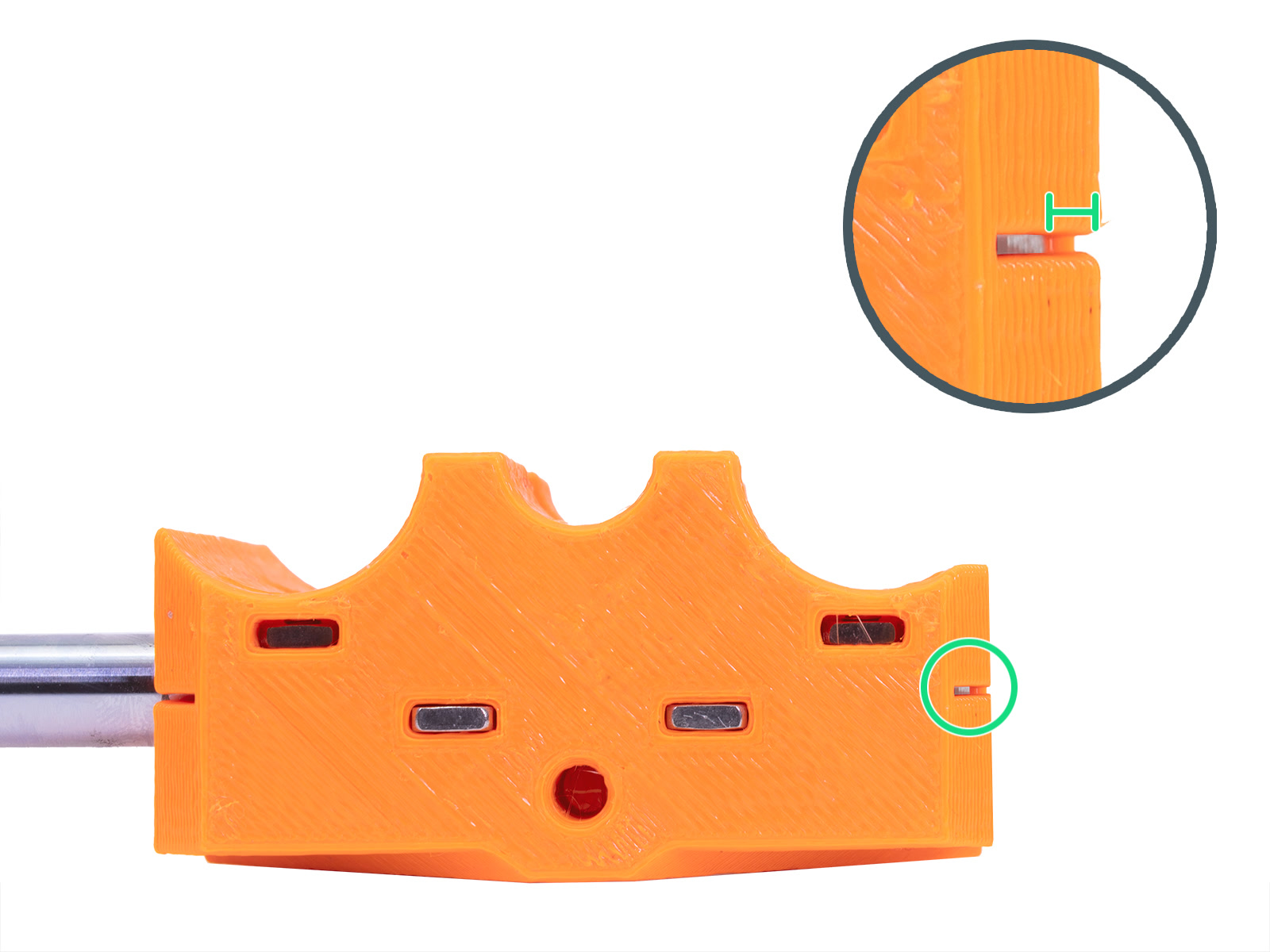
- The smooth rods of the X-axis are inserted all the way to the extruder plastic parts (left picture). X-end and extruder parts have inspection holes to check (green circle).
- The 10mm linear bearings of the Z-axis are slightly below the plastic parts (~0.75 mm) that secure them and equal on both bearings.
- The foam pad legs are stuck only to the aluminum extrusions, and not to the plastic front/back plate.
- Make sure the heatbed and nozzle are cooled down to room temperature!
Checking each axis
Start by removing the flexible steel sheet. This is a laser-cut square and we will use it for a later step. Then home the printer from Calibration -> Auto home, on the LCD menu and Disable steppers by restarting the printer using the button on the LCD module or by navigating to Settings -> Disable Steppers.
Y-axis
Any noticeable deviation in this step is very rare but ensures following tests and done on a flat surface. If you do find any deviation above ~0.5-1 mm, continue through the whole procedure, then do this check again before contacting support.
- With the steppers disabled, slide the tip of the nozzle to the center dotted line with the printed "100" mm mark.
- Turn the threaded rod of the Z-axis by hand to move the nozzle closer to the bed (~1mm), so it is almost touching it (purple ruler).
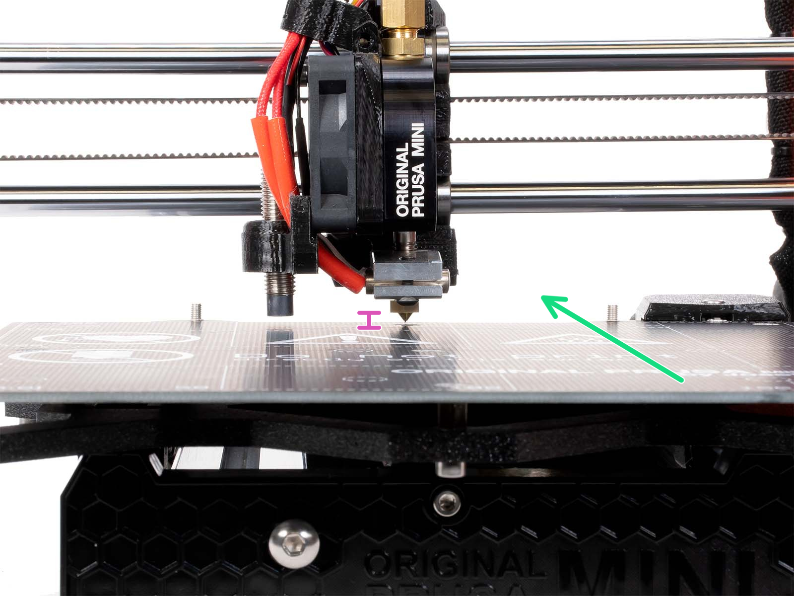 |  |
- While looking at the distance between the nozzle and heat bed, slide the bed from one extreme to another (green arrows) and see if there is any deviation. Make sure you do not push down on the bed while sliding it!
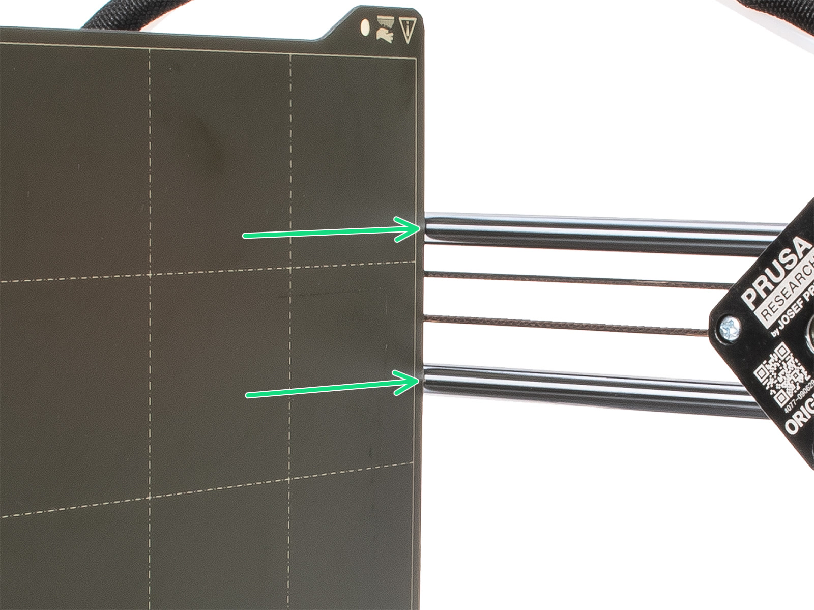
YZ-axis
This checks the bed (Y-axis) against the Z-axis, ensures the smooth X-rods are parallel, and perpendicular to the Z-axis with the nozzle pointing directly down.
- While steppers are still disabled, move the print head to the right of the X-axis.
- Move the heatbed to the front of the printer.
- Navigate the LCD menu to Settings -> Move axis -> Move Z and turn to knob clockwise until the print head/X-gantry is roughly 100-150 mm above the bed.
- Place the steel sheet vertically on the bed, with the rear notch facing down. When pushed against the X-axis rods, the steel sheet should touch both smooth rods simultaneously.
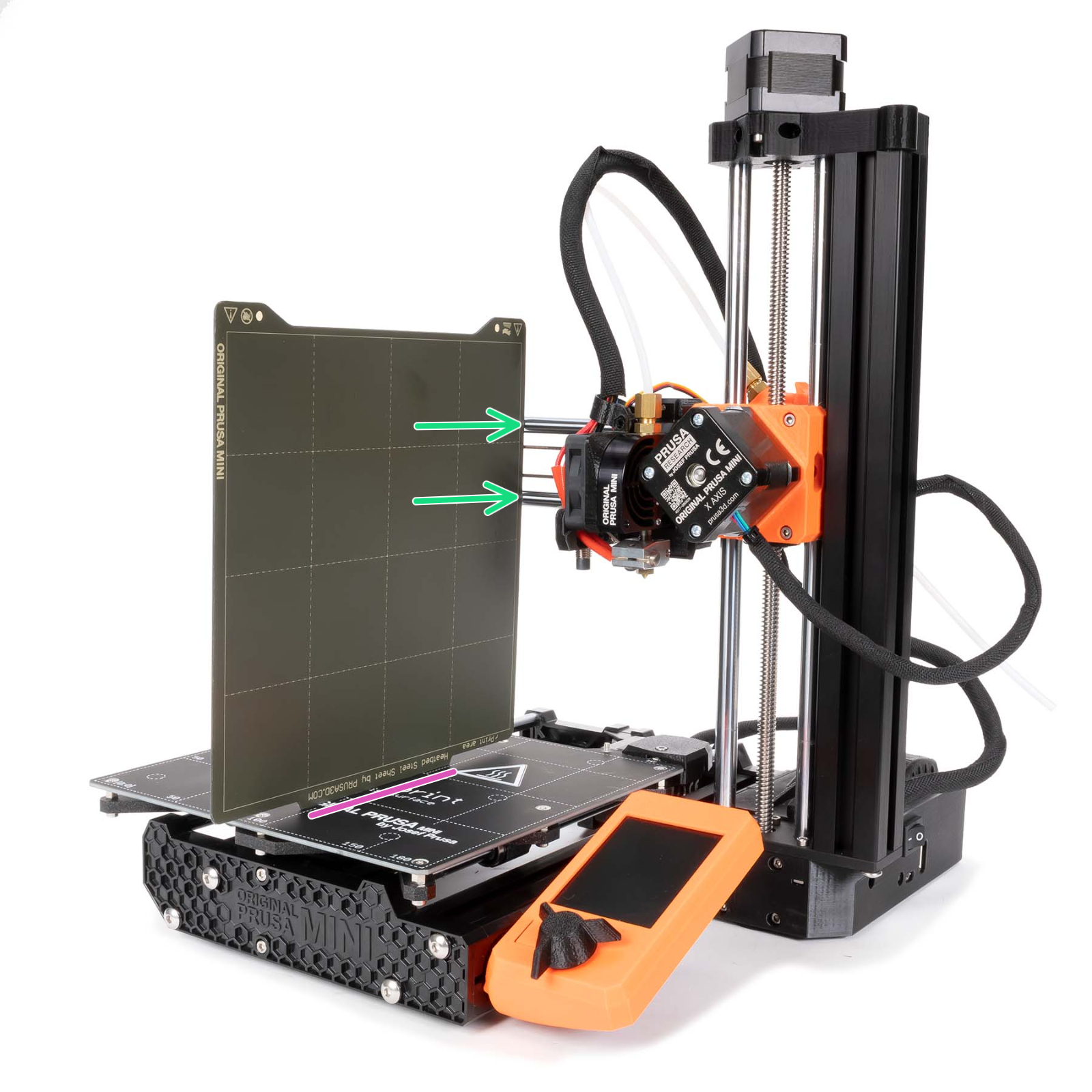
- If they do not touch simultaneously, carefully twist the X-end plastic part so they do. You may have to loosen the two screws on the side of the X-end, securing it to the rods, to smoothly twist it.
 |  |
- Navigate to Settings -> Disable Steppers, and move the print head to the left of the X-axis.
- Confirm this two more times with the steel sheet on the printed dotted line next to "50" and "150".
 |  |
XZ-axis
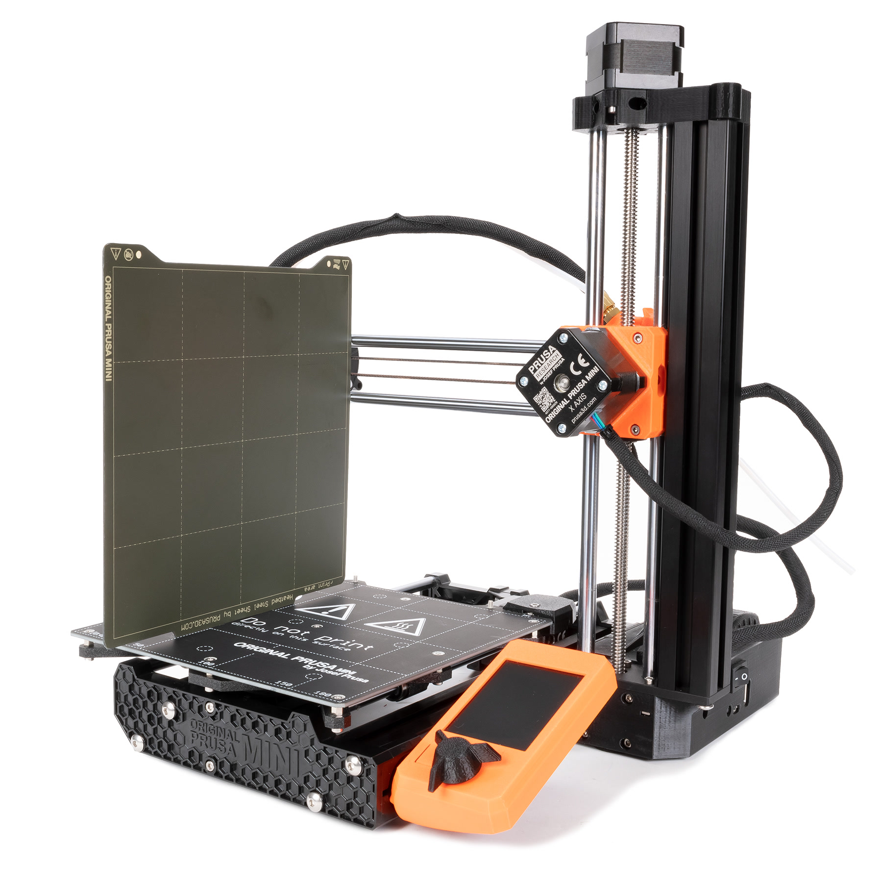
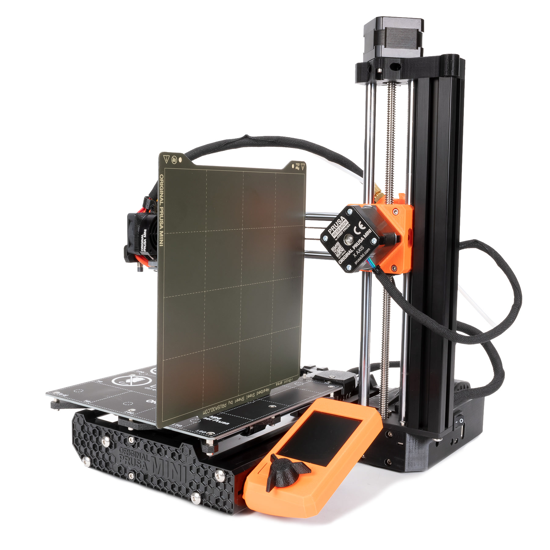
Here we will make sure the nozzle holds the same distance to the heatbed across the full length of the X-axis. First Layer Calibration (MINI/MINI+) will also not have an even thickness across its entire length and be flatter/more squished on one side of the bed and the other.
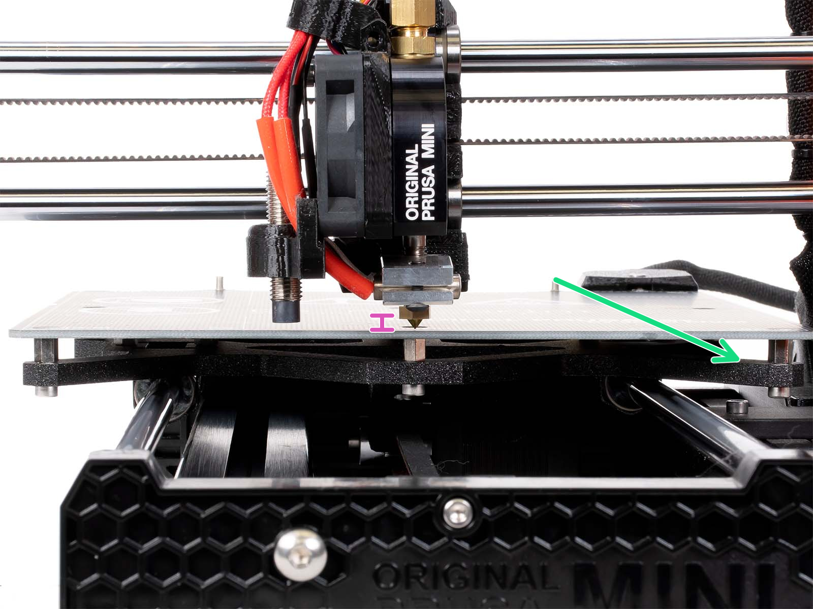
- Home the printer (LCD menu -> Calibration -> Auto home) which moves the print head to the far right and close to the bed (left picture). Notice the distance between the heatbed and the tip of the nozzle (purple ruler left picture).
- Disable steppers by restarting the printer or navigating to Settings -> Disable Steppers.
- Slide the print head across the bed by hand to the left and see if there is any change in the distance. The tip of the nozzle should have the same distance to the print surface across the entire length of the X-axis.
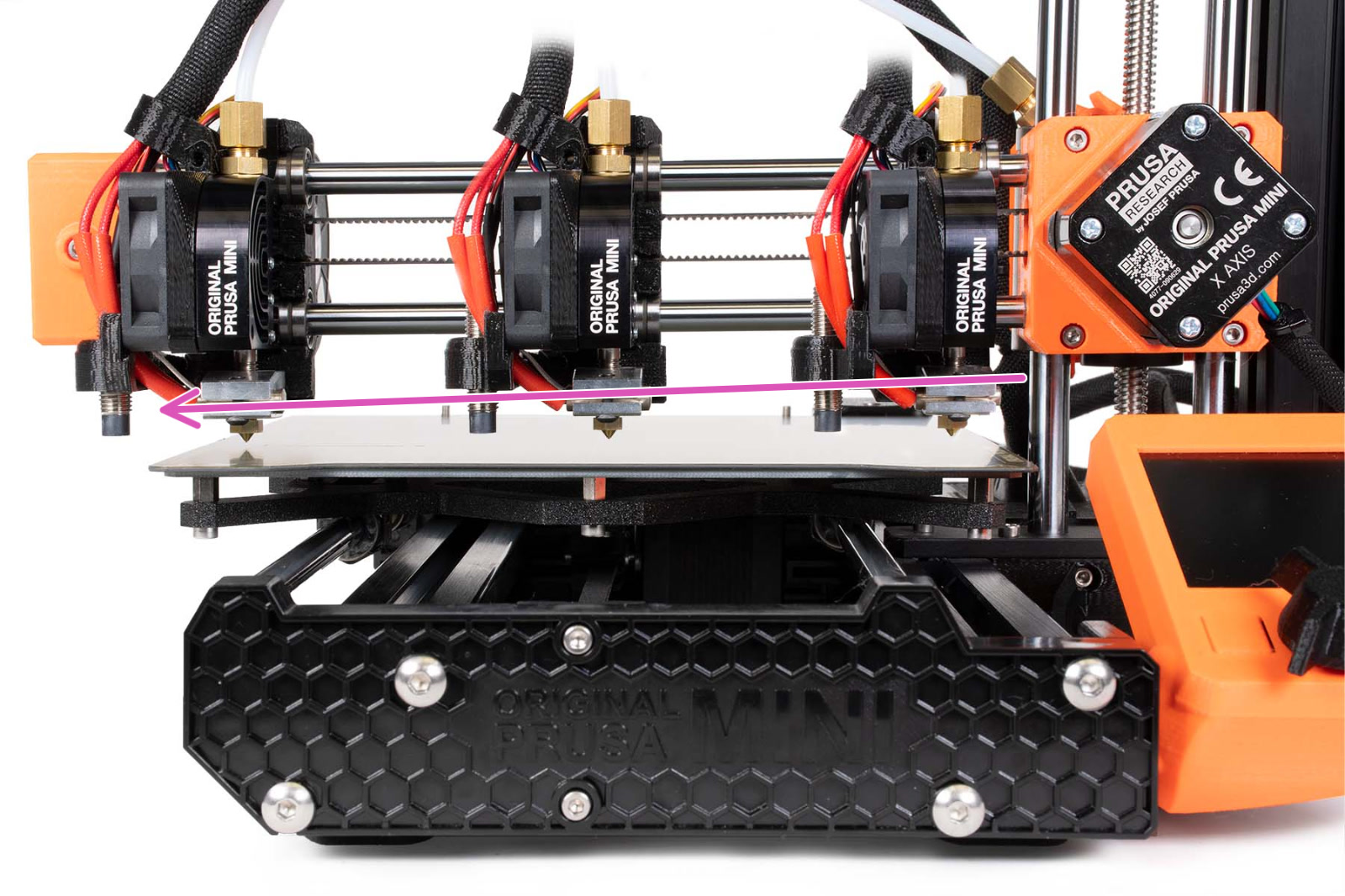 Printer with an XZ skew to the left.
XZ-axis correction
We will correct this skew by resetting the Y-axis extrusion. This requires a 3mm Allen key.
- Home the printer, by navigating to Calibration -> Auto home, on the LCD menu.
- Disable steppers by restarting the printer or navigating to Settings -> Disable Steppers.
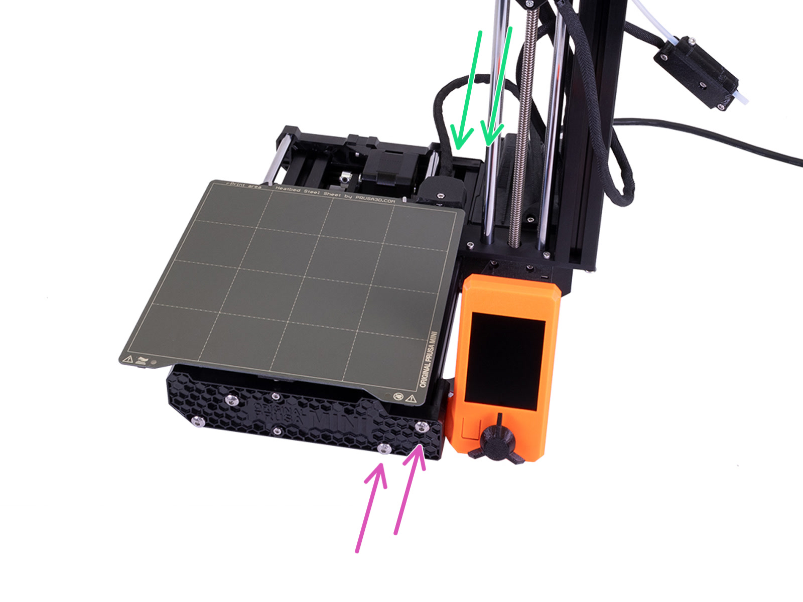
- Using a 3 mm Allen key, loosen the two screws closest to the Z-axis, on the front and backplate (purple and green arrows). Do not remove the screws, just loosen them roughly a quarter turn.
- Carefully press/tap the Z-tower towards or away from the bed (blue arrows) depending on the direction of the skew. You can damage the printer if you use too much force.
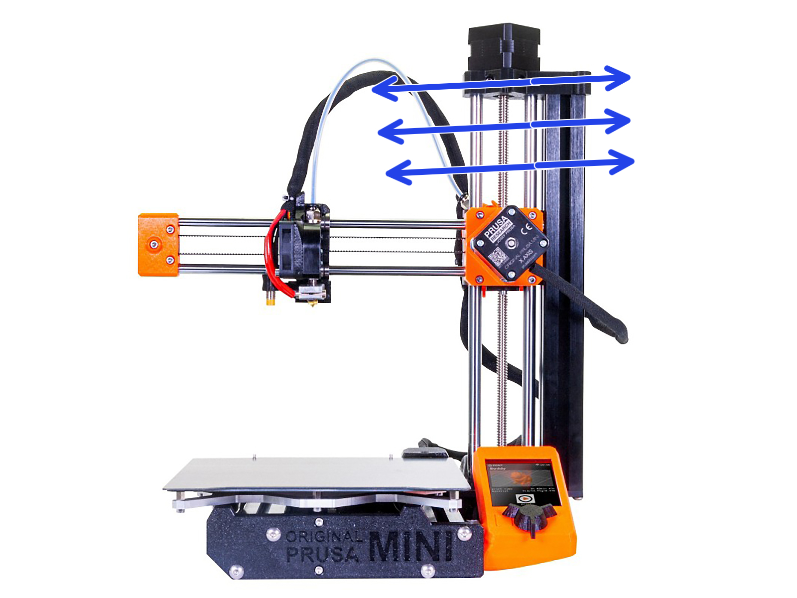
- Move the nozzle across the bed to make sure it has the same distance to the bed across the whole X-axis (green arrow).
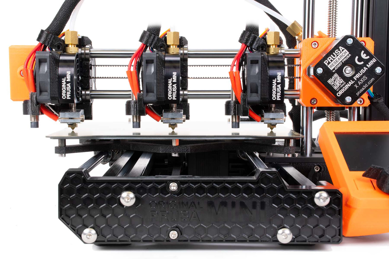
Corrected printer with no skew.
- Once satisfied, secure the 4 screws on the front/backplate again, which you loosened in Step 3.
Fine-tuning the XZ-axis
With a very small deviation (0.5 - 1 mm / 0.02 - 0.04 in), it can be difficult to dial it in using the method above. Use this method to fine-tune, but it is important that the two end screws do not differ more than 0.5-1mm in how much they protrude.
Downward adjustment
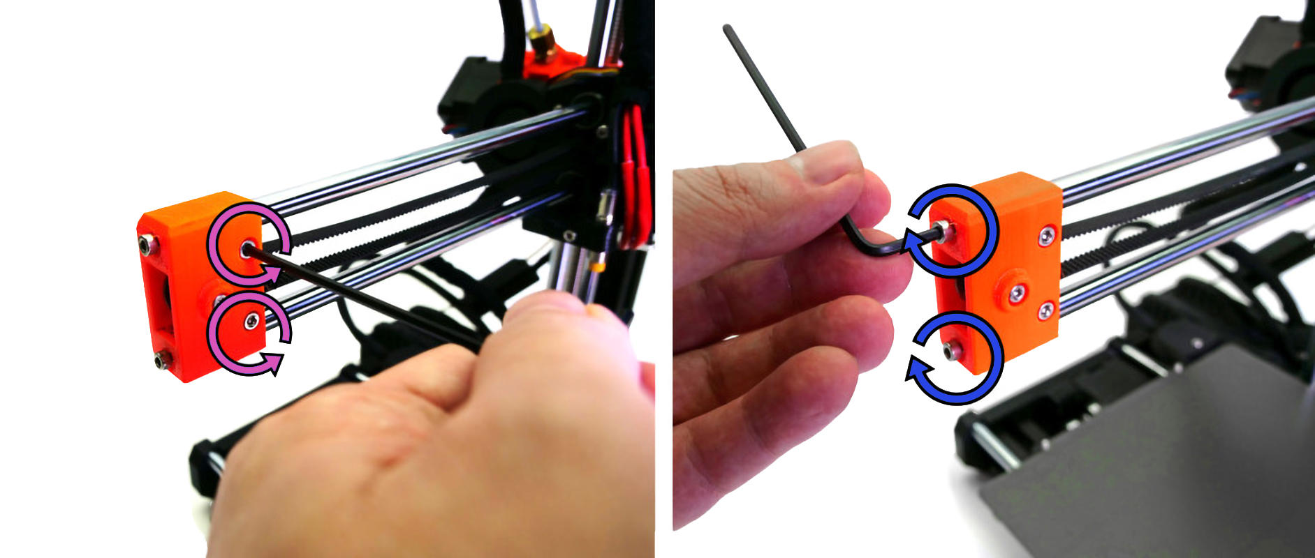
- Turn the two screws on the side of the idler-holder (purple arrows) counterclockwise.
- Turn the top screw on the end clockwise (top blue arrow). This will bring the X arm down, correcting the skew.
- Secure the idler-holder again by turning the screws on the side clockwise.
Upwards adjustment
- Loosen the two screws on the side of the idler-holder (purple arrows) by turning them counterclockwise.
- Turn the bottom screw on the end clockwise (bottom blue arrow). This will bring the X arm up, correcting a slight skew in this direction.
- Secure the idler-holder again by turning the screws on the side clockwise.
17 comments
I've been trying to validate the X axis test for 2/3 days, I've tried everything but it keeps failing.
I noticed that the axis is slightly inclined, because the extruder head, moving along the X axis, tends to get closer to the printing bed. I'm following the steps in point 6, but the test keeps failing.
I'm very sad and disappointed about this, because assembling the printer has been very tiring and I still can't even do a "regular" print test...
for cases like this, it is best to contact support either by pressing the chat now button in the lower right corner of the page, or send an email to [email protected] so you can show them photos and they can walk you through steps to resolve this issue.
My Y-axis has 1,1mm deviation but this tutorial do not describe how to compensate it. Any tips? I'm truing to square my MINI+ as much as possible.
Try retigntening the heatbed screws according to the assembly manual. If this does not solve the issue, make pictures and videos and share with out technical support.