- English
- Deutsch
- Français
- Home
- Risoluzione dei problemi
- Risoluzione dei problemi della stampante
- Loadcell troubleshooting
Loadcell troubleshooting
- Risoluzione problemi qualità di stampa
- Codici errore QR
- Risoluzione dei problemi della stampante
- Surriscaldamento A64 #10207 (SL1/SL1S)
- Controllo della temperatura ambiente (MK3/MK3S)
- Temperatura ambiente troppo fredda #10703 (SL1/SL1S)
- Temperatura ambiente troppo alta #10702 (SL1/SL1S)
- Si è verificato un errore inaspettato #10701 (SL1)
- Impossibile eseguire questa azione #10506 (SL1/SL1S)
- Allocazione BBF non riuscita #17531 (XL)
- Allocazione BBF non riuscita #26531 (MK4S) #13531 (MK4) #21531 (MK3.9) #23531 (MK3.5)
- Inizializzazione BBF non riuscita #17532 (XL)
- Inizializzazione BBF non riuscita #26532 (MK4S) #13532 (MK4) #21532 (MK3.9) #23532 (MK3.5)
- Bed maxtemp error #26205 (MK4S) #13205 (MK4) #21205 (MK3.9) #23205 (MK3.5)
- Bed mintemp error #26207 (MK4S) #13207 (MK4) #21207 (MK3.9) #23207 (MK3.5)
- Errore Preriscaldamento piano #26201 (MK4S) #13201 (MK4) #21201 (MK3.9) #23201 (MK3.5)
- Bed thermal runaway #26203 (MK4S) #13203 (MK4) #21203 (MK3.9) #23203 (MK3.5)
- Fusibile bruciato (MINI)
- Fusibile bruciato (MK2S/MK2.5/MK2.5S)
- Fusibile bruciato (MK3/MK3S/MK3S+)
- Fusibile bruciato (MK4/S, MK3.9/S)
- Blue Screen of Death (BSOD)
- Problema della scheda Boost #10320 (SL1S)
- Stampante bloccata (SL1/SL1S)
- Il progetto di calibrazione non è valido #10543 (SL1/SL1S)
- Impossibile copiare progetto #10704 (SL1/SL1S)
- Impossibile ottenere il canale di aggiornamento. #10514 (SL1)
- Impossibile leggere il progetto #10539 (SL1/SL1S)
- Impossibile rimuovere il progetto #10545 (SL1/SL1S)
- Ugello otturato (MK4)
- Ugello otturato (XL)
- Ugello/hotend otturato (MINI/MINI+)
- Ugello/hotend otturato (MK3.5/S, MK3S+, MK2.5S)
- Registrazione a Connect fallita
- Registrazione a Connect fallita #12401 (MINI)
- Registrazione a Connect fallita #17401 (XL)
- Registrazione a Connect fallita #21401 (MK3.9)
- Registrazione a Connect fallita #23401 (MK3.5)
- Registrazione a Connect fallita #26401 (MK4S) #13401 (MK4)
- Directory non vuota #10546 (SL1/SL1S)
- Pannello UV LED non connesso #10321 (SL1/SL1S)
- Test display fallito #10120 (SL1/SL1S)
- Errore Dwarf #17502 (XL)
- Errore Dwarf #17503 (XL)
- Ricezione EEPROM I2C occupata #17316 (XL)
- Ricezione EEPROM I2C occupata #26316 (MK4S) #13316 (MK4) #21316 (MK3.9) #23316 (MK3.5)
- Arresto di emergenza #12510 (MINI)
- Emergency stop #17510 (XL)
- Arresto di emergenza #26510 (MK4S) #13510 (MK4) #21510 (MK3.9) #23510 (MK3.5)
- Errore ESP #17504 (XL)
- Errore ESP #17505 (XL)
- ESP error #17506 (XL)
- Errore ESP #26504 (MK4S) #13504 (MK4) #21504 (MK3.9) #23504 (MK3.5)
- Errore ESP #26505 (MK4S) #13505 (MK4) #21505 (MK3.9) #23505 (MK3.5)
- Errore ESP #26506 (MK4S) #13506 (MK4) #21506 (MK3.9) #23506 (MK3.5)
- ESP non collegato #17533 (XL)
- Atteso surriscaldamento #10714 (SL1/SL1S)
- Flash SPI esterno W25X20CL/xFLASH non risponde - errore
- Blob estrusore
- Extruder Maxtemp error #17206 (XL)
- Extruder Mintemp error #17208 (XL)
- Rumori Estrusore
- Errore di preriscaldamento dell'estrusore #17202 (XL)
- La temperatura dell'estrusore non corrisponde #17210 (XL)
- Extruder thermal runaway #17204 (XL)
- L'estrusione è stata interrotta a metà stampa (Heat creep)
- Reset di fabbrica (MINI)
- Ripristino delle impostazioni di fabbrica (MK2S/MK2.5S/MK3S)
- Ripristino di fabbrica (MK4/S, MK3.9/S, MK3.5/S, MINI/+, XL)
- Factory Reset (MMU)
- Ripristino di fabbrica (MMU2S con firmware pre 1.0.6)
- Reset di fabbrica (SL1/SL1S)
- Impossibile leggere il file di configurazione #10505 (SL1)
- Calibrazione Z non riuscita (MK3S/MK2.5S)
- Guasto ventola #10106 (SL1/SL1S)
- Avviso ventola #10713 (SL1/SL1S)
- Scaricamento filamento non riuscito (MINI/MINI+)
- Il filamento non carica
- Il filamento non viene caricato (MK4/S, MK3.9/S)
- Il filamento non viene caricato (XL)
- Sensore filamento (MK4, MK3.9, XL)
- File già esistente! #10520 (SL1)
- File non trovato #10518 (SL1/SL1S)
- Errore del file system #12613 (MINI/MINI+)
- Errore del file system #26613 (MK4S) #13613 (MK4) #21613 (MK3.9) #23613 (MK3.5)
- Setup e troubleshooting FINDA
- FINDA: Filamento bloccato #04102 (MMU)
- Firmware della memoria interna corrotto! #12608 (MINI)
- Firmware missing #17612 (XL)
- Aggiornamento del firmware richiesto #26701 (MK4S) #13701 (MK4) #21701 (MK3.9) #23701 (MK3.5)
- Problematiche di aggiornamento firmware (MK2.5S/MK3S+/MMU2S/MMU3)
- Il primo layer non aderisce (SL1/SL1S)
- Errore cancellazione flash #12605 (MINI/MINI+)
- Flash erase error #17605 (XL)
- Errore cancellazione flash #26605 (MK4S) #13605 (MK4) #21605 (MK3.9) #23605 (MK3.5)
- FW in internal flash corrupted #17608 (XL)
- Firmware della memoria interna corrotto #26608 (MK4S) #13608 (MK4) #21608 (MK3.9) #23608 (MK3.5)
- Verifica Hash non riuscita #12607 (MINI/MINI+)
- Verifica Hash non riuscita #17607 (XL)
- Verifica Hash non riuscita #26607 (MK4S) #13607 (MK4) #21607 (MK3.9) #23607 (MK3.5)
- Piano riscaldato non si scalda correttamente
- Sovracorrente della porta del piano riscaldato #26309 (MK4S) #13309 (MK4) #21309 (MK3.9) #23309 (MK3.5)
- La temperatura del piano riscaldato non corrisponde #17209 (XL)
- Heatbreak Maxtemp error #17212 (XL)
- Heatbreak MAXTEMP Error #26212 (MK4S) #13212 (MK4) #21212 (MK3.9)
- Heatbreak Mintemp error #17211 (XL)
- Heatbreak MINTEMP Error #26211 (MK4S) #13211 (MK4) #21211 (MK3.9)
- Errore Homin #12301 (MINI)
- Errore Homing X #12304 (MINI/MINI+)
- Homing error X #17304 (XL)
- Errore Homing X #26304 (MK4S) #13304 (MK4) #21304 (MK3.9) #23304 (MK3.5)
- Errore Homing Y #12305 (MINI/MINI+)
- Homing error Y #17305 (XL)
- Errore Homing Y #26305 (MK4S) #13305 (MK4) #21305 (MK3.9) #23305 (MK3.5)
- Errore Homing Z #17301 (XL)
- Errore Homing Z #23301 (MK3.5)
- Errore Homing Z #26301 (MK4S) #13301 (MK4) #21301 (MK3.9)
- La ventola dell'hotend non gira
- Sovracorrente Riscaldatore Hotend #17322
- Hotend maxtemp error #23206 (MK3.5)
- Hotend mintemp error #23208 (MK3.5)
- Hotend mintemp error #26208 (MK4S) #13208 (MK4) #21208 (MK3.9)
- Hotend preheat error #23202 (MK3.5)
- Errore di preriscaldamento dell'hotend #26202 (MK4S) #13202 (MK4) #21202 (MK3.9)
- La temperatura dell'hotend non corrisponde #13210 (MK3.9/MK4) #23210 (MK3.5)
- La temperatura dell'hotend non corrisponde #23210 (MK3.5)
- Hotend thermal runaway #23204 (MK3.5)
- Hotend thermal runaway #26204 (MK4S) #13204 (MK4) #21204 (MK3.9)
- Ricezione I2C non riuscita #17315 (XL)
- Ricezione I2C non riuscita #26315 (MK4S) #13315 (MK4) #21315 (MK3.9) #23315 (MK3.5)
- Timeout ricezione I2C #17317 (XL)
- Timeout ricezione I2C #26317 (MK4S) #13317 (MK4) #21317 (MK3.9) #23317 (MK3.5)
- Ricezione I2C non definito #17318 (XL)
- Ricezione I2C non definita #26318 (MK4S) #13318 (MK4) #21318 (MK3.9) #23318 (MK3.5)
- Invio I2C Occupato#17312 (XL)
- Invio I2C occupato #26312 (MK4S) #13312 (MK4) #21312 (MK3.9) #23312 (MK3.5)
- Invio I2C non riuscito #17311 (XL)
- Invio I2C non riuscito #26311 (MK4S) #13311 (MK4) #21311 (MK3.9) #23311 (MK3.5)
- Timeout invio I2C #17313 (XL)
- Timeout invio I2C #26313 (MK4S) #13313 (MK4) #21313 (MK3.9) #23313 (MK3.5)
- Invio I2C non definito #17314 (XL)
- Invio I2C non definito #26314 (MK4S) #13314 (MK4) #21314 (MK3.9) #23314 (MK3.5)
- Impostore! Firma falsa #17606 (XL)
- Modello stampante errato #10705 (SL1/SL1S)
- Memoria interna piena #10516 (SL1/SL1S)
- Chiave API invalida #10405 (SL1/SL1S)
- Dimensione FW non valida su USB #12603 (MINI/MINI+)
- Dimensione FW non valida su USB #26603 (MK4S) #13603 (MK4) #21603 (MK3.9) #23603 (MK3.5)
- Invalid FW size on USB flash drive #17603 (XL)
- Calibrazione sensore filamento IR (MMU3, MMU2S)
- Risoluzione dei problemi del Sensore del filamento IR (MINI/MINI+)
- Risoluzione dei problemi del sensore del filamento IR (MK2.5S, MK3S)
- Schermo LCD non funzionante
- Errore Memoria LED #17529 (XL)
- Errore Memoria LED #26529 (MK4S) #13529 (MK4) #21529 (MK3.9) #23529 (MK3.5)
- Live adjust Z non salvata
- Carico sull'estrusore fallito #04108 (MMU)
- Configurazione errata della cella di carico #17527 (XL)
- Configurazione errata della cella di carico #26527 (MK4S) #13527 (MK4) #21527 (MK3.9)
- Misurazione della cella di carico non riuscita #17526 (XL)
- Misurazione della cella di carico non riuscita #26526 (MK4S) #13526 (MK4) #21526 (MK3.9)
- Cella di carico non calibrata #17523 (XL)
- Cella di carico non calibrata #26523 (MK4S) #13523 (MK4) #21523 (MK3.9)
- Errore tara cella di carico #17524 (XL)
- Errore Tara della cella di carico #26524 (MK4S) #13524 (MK4) #21524 (MK3.9)
- Tara della cella di carico non riuscita #17525 (XL)
- Tara della cella di carico non riuscita #26525 (MK4S) #13525 (MK4) #21525 (MK3.9)
- Timeout cella di carico #17528 (XL)
- Timeout cella di carico #26528 (MK4S) #13528 (MK4) #21528 (MK3.9)
- Loadcell troubleshooting
- Testing the loadcell
- Bolts that interact with the loadcell
- Loadcell white pad - visual check
- Log dei dati su linea seriale (MMU2S)
- Rumori forti dalla stampante (SL1/SL1S)
- Test sensore M.I.N.D.A./SuperPINDA (MINI/MINI+)
- Timeout richiesta Marlin #17530 (XL)
- Timeout richiesta Marlin #26530 (MK4S) #13530 (MK4) #21530 (MK3.9) #23530 (MK3.5)
- Avviso di maschera non disponibile #10709 (SL1/SL1S)
- Maxtemp error piano #12205 (MINI)
- Maxtemp error testina di stampa #12206 (MINI)
- MCU Maxtemp Error #17213 (XL)
- Mintemp error piano #12207 (MINI)
- Mintemp error testina di stampa #12208 (MINI)
- Sensore PINDA disallineato (MK2/S)
- Parti mancanti (SL1/SL1S)
- MK3S continua a richiedere il cambio del filamento
- MMU MCU Sottotensione #04307 (MMU)
- Sovracorrente MMU #26310 (MK4S) #13310 (MK4) #21310 (MK3.9) #23310 (MK3.5)
- Idler MMU2S non riesce a muoversi liberamente
- Significato LED MMU2S
- Selettore MMU2S non si muove
- Errore nel piano modulare #17250 (XL)
- Errore nel piano modulare #17251 (XL)
- Errore nel piano modulare #17252 (XL)
- Errore nel piano modulare #17253 (XL)
- Errore nel piano modulare #17254 (XL)
- Errore nel piano modulare #17255 (XL)
- Errore nel piano modulare #17256 (XL)
- Errore piano modulare #17257 (XL)
- Modular bed error #17302 (XL)
- Modular bed error #17303 (XL)
- Errore Piano Modulare #17319 (XL)
- Errore Piano Modulare #17320 (XL)
- Errore piano modulare #17501 (XL)
- Utilizzo del multimetro
- Nessun file su USB #12604 (MINI/MINI+)
- Nessun file da ristampare #10508 (SL1)
- Nessun FW nella memoria interna #12612 (MINI/MINI+)
- Nessun FW nella memoria interna #26612 (MK4S) #13612 (MK4) #21612 (MK3.9) #23612 (MK3.5)
- Nessun FW su USB #26604 (MK4S) #13604 (MK4) #21604 (MK3.9) #23604 (MK3.5)
- No FW on USB flash drive #17604 (XL)
- Non connesso alla rete #10402 (SL1/SL1S)
- Non abbastanza strati #10540 (SL1/SL1S)
- Resina non sufficiente #10706 (SL1/SL1S)
- Pulizia dell'ugello non riuscita (MK4, MK3.9)
- Pulizia ugello non riuscita (XL)
- L'ugello ha colpito il piano riscaldato
- Sovracorrente del riscaldatore dell'ugello #23308 (MK3.5)
- Sovracorrente del riscaldatore dell'ugello #26308 (MK4S) #13308 (MK4) #21308 (MK3.9)
- Avviso oggetto tagliato #10710 (SL1/SL1S)
- Apertura progetto non riuscito #10504 (SL1/SL1S)
- Memoria esaurita #17507 (XL)
- Memoria esaurita #26507 (MK4S) #13507 (MK4) #21507 (MK3.9) #23507 (MK3.5)
- Test Sensore P.I.N.D.A./SuperPINDA
- Parametri fuori portata #10707 (SL1/SL1S)
- Perno non raggiunto #17107 (XL)
- Buffer PNG Pieno #17508 (XL)
- Buffer PNG Pieno #26508 (MK4S) #13508 (MK4) #21508 (MK3.9) #23508 (MK3.5)
- Errore Preriscaldamento piano #12201 (MINI)
- Errore preriscaldamento testina di stampa #12202 (MINI)
- Precaricamento fallito #10503 (SL1/SL1S)
- Esempi di stampa mancanti #10523 (SL1/SL1S)
- La ventola di stampa non gira
- La stampante non si accende o continua a spegnersi
- Analisi del progetto fallita #10542 (SL1/SL1S)
- Progetto corrotto #10541 (SL1/SL1S)
- Risoluzione dei problemi di PrusaLink
- Errore Puppy #17511 (XL)
- Errore Puppy #17512 (XL)
- Errore Puppy #17513 (XL)
- Errore Puppy #17514 (XL)
- Errore Puppy #17515 (XL)
- Errore Puppy #17516 (XL)
- Errore Puppy #17517 (XL)
- Errore Puppy #17518 (XL)
- Errore Puppy #17519 (XL)
- Errore Puppy #17520 (XL)
- Errore Puppy #17521 (XL)
- Errore Puppy #17522 (XL)
- Errore API remoto #10407 (SL1/SL1S)
- Resina insufficiente #10712 (SL1/SL1S)
- Misurazione resina non riuscita #10124 (SL1/SL1S)
- Errore sensore resina #10307 (SL1/SL1S)
- Resina troppo alta #10109 (SL1/SL1S)
- Resina troppo bassa #10108 (SL1/SL1S)
- G-code di prova
- Salvare il file log (SL1/SL1S)
- La scheda SD non funziona
- Schede SD e unità USB
- Autotest fallito (XL multi-tool)
- Autotest fallito (XL)
- Verifica della firma non riuscita #12606 (MINI/MINI+)
- Verifica della firma non riuscita #26606 (MK4S) #13606 (MK4) #21606 (MK3.9) #23606 (MK3.5)
- SL1 Errore del meccanismo basculante
- Spaghetti monster
- Quadratura della MINI
- Spiegazione dei LED di stato (MK4/XL)
- Spiegazione del LED di stato (MMU3)
- Rilevamento del filamento bloccato #26101 (MK4S) #13101 (MK4) #21101 (MK3.9) #17108 (XL)
- Filamento aggrovigliato
- La temperatura del piano riscaldato non corrisponde #12209 (MINI/MINI+)
- La temperatura della testina di stampa non corrisponde #12210 (MINI/MINI+)
- Temperatura fuori portata #10208 (SL1/SL1S)
- Thermal runaway piano #12203 (MINI)
- Thermal runaway testina di stampa #12204 (MINI)
- Cortocircuito driver TMC #04304 (MMU)
- Cortocircuito driver TMC #04314 (MMU)
- Cortocircuito driver TMC #04324 (MMU)
- Offset dello strumento fuori dai limiti #17104 (XL)
- Errore Toolchanger #17101 (XL)
- Problema al Tool-changer (XL multi-tool)
- Controllo torre fallito #10118 (SL1/SL1S)
- Non autorizzato #10406 (SL1/SL1S)
- Under-extrusion (Nextruder printers)
- Errore imprevisto #10501 (SL1/SL1S)
- Errore MC imprevisto #10306 (SL1/SL1S)
- Modello di stampante sconosciuto #10323 (SL1/SL1S)
- Versione BBF non supportata #12614 (MINI/MINI+)
- Versione BBF non supportata #26614 (MK4S) #13614 (MK4) #21614 (MK3.9) #23614 (MK3.5)
- Unsupported Buddy FW #17611 (XL)
- Unsupported firmware BBF file #17614 (XL)
- Unsupported printer model #17610 (XL)
- Tipo di stampante non supportato #12610 (MINI/MINI+)
- Tipo di stampante non supportato #26610 (MK4S) #13610 (MK4) #21610 (MK3.9) #23610 (MK3.5)
- Versione della stampante non supportata #12611 (MINI/MINI+)
- Versione stampante non supportata #26611 (MK4S) #13611 (MK4) #21611 (MK3.9) #23611 (MK3.5)
- Sovracorrente Unità USB #17307 (XL)
- Sovracorrente Unità USB #26307 (MK4S) #13307 (MK4) #21307 (MK3.9) #23307 (MK3.5)
- Unità USB non rilevata #10528 (SL1/SL1S)
- USB flash drive not connected #17602 (XL)
- USB flash error #17613 (XL)
- USB non connessa #12602 (MINI/MINI+)
- USB non connessa #26602 (MK4S) #13602 (Mk4) #21602 (MK3.9) #23602 (MK3.5)
- Sovracorrente della porta USB #17306 (XL)
- Sovracorrente della porta USB #26306 (MK4S) #13306 (MK4) #21306 (MK3.9) #23306 (MK3.5)
- Errore temperatura LED UV #10209 (SL1/SL1S)
- Errore voltaggio LED UV #10309 (SL1)
- Vibrazioni durante la stampa (MK3S+/MK2.5S)
- Modello stampante errato #10544 (SL1/SL1S)
- Errata revisione del Motion Controller #10301 (SL1)
- Posizione XY non valida #17106 (XL)
- Sonda XY instabile #17105 (XL)
- Messaggi di Errore di Stampa
The Original Prusa MK4/S and MK3.9/S are equipped with a loadcell. This component incorporated in the Nextruder heatsink detects if the nozzle is close enough to the steel sheet for printing.
The only adjustment needed for the loadcell is during the selftest. After that, the first layer calibration is always done automatically during the mesh bed leveling. This avoids any damage that would be caused by the nozzle digging into the steel sheet.
Below are our recommended steps for loadcell troubleshooting.
Testing the loadcell
During the selftest, the loadcell will be tested. The printer screen shows the instructions for testing it.
Alternatively, the loadcell testing can be initiated in LCD Menu -> Control -> Calibration & Tests -> Loadcell Test.
During the test, you will be asked to tap the nozzle at a specific time, and a progress bar shown on the screen is filled, depending on the pressure applied to the loadcell. If the bar is not filled, is filled irregularly, or the printer shows any errors, please contact our customer support.
 |  |
Bolts that interact with the loadcell
Some of the Nextruder bolts, if too tight, might generate extra forces that can be sensed by the loadcell, skewing its readings, hence potentially causing the issue.
Check if slightly loosening the following bolts, while having the parts still tight and secured in place, can solve the issue.
Preliminary steps (MK4S, MK3.9S)
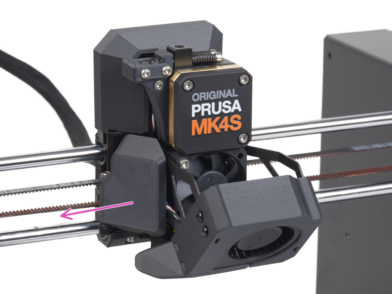
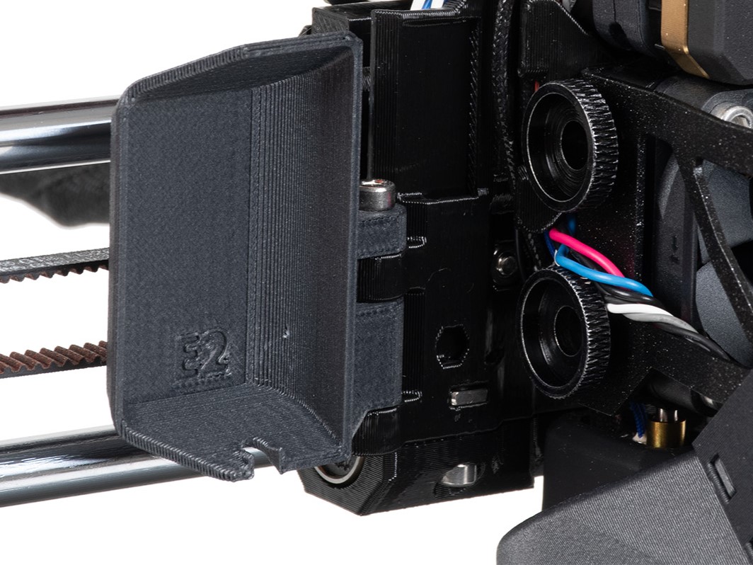
On MK4S and MK3.9S, it is necessary to perform the following preliminary steps to access the hotend fan bolts.
- Rotate the fan-door-cover to open it completely.
 |  |
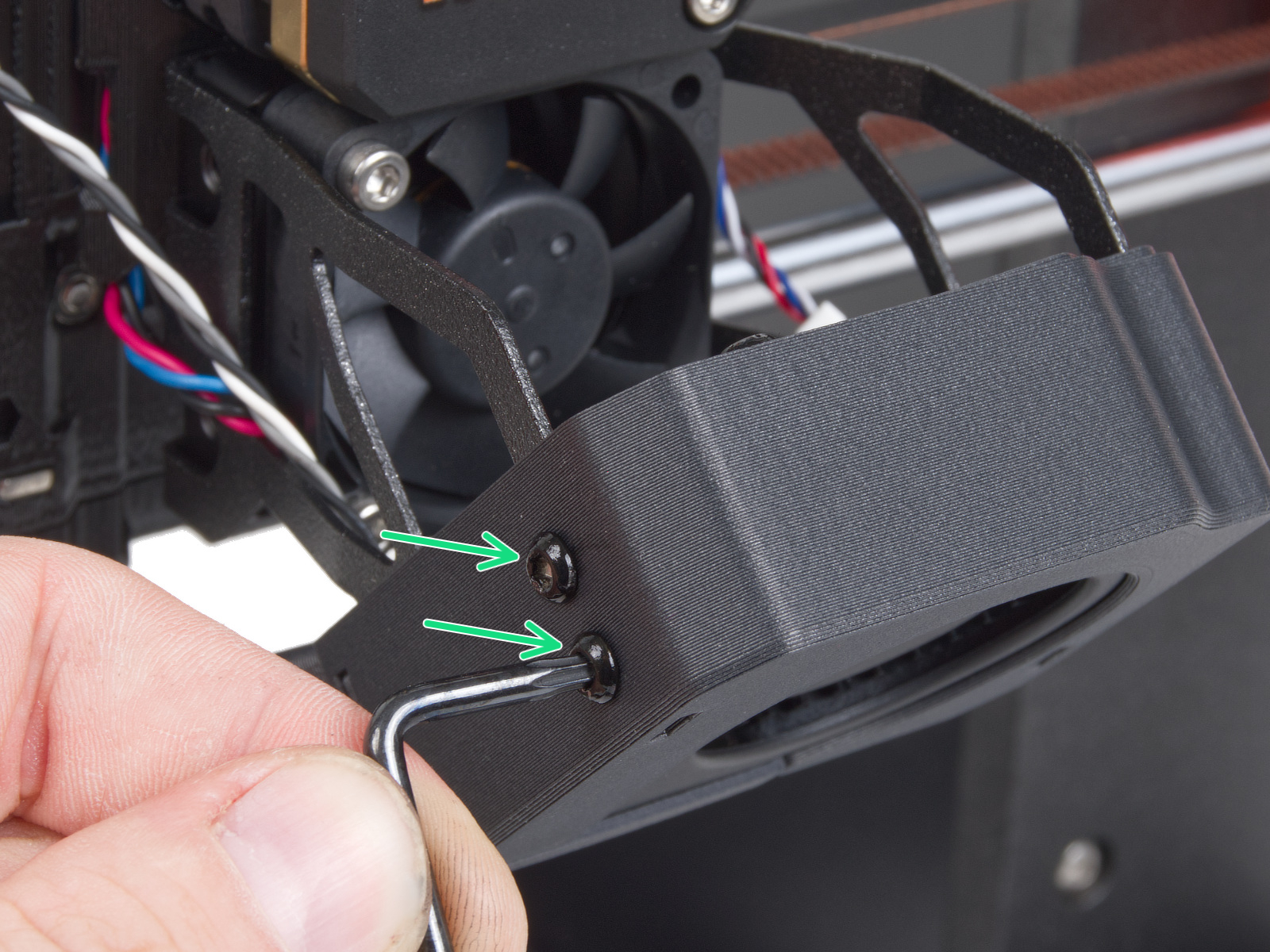
- Loosen 4x M3x5rT screws, two on the left and two on the right.
 | 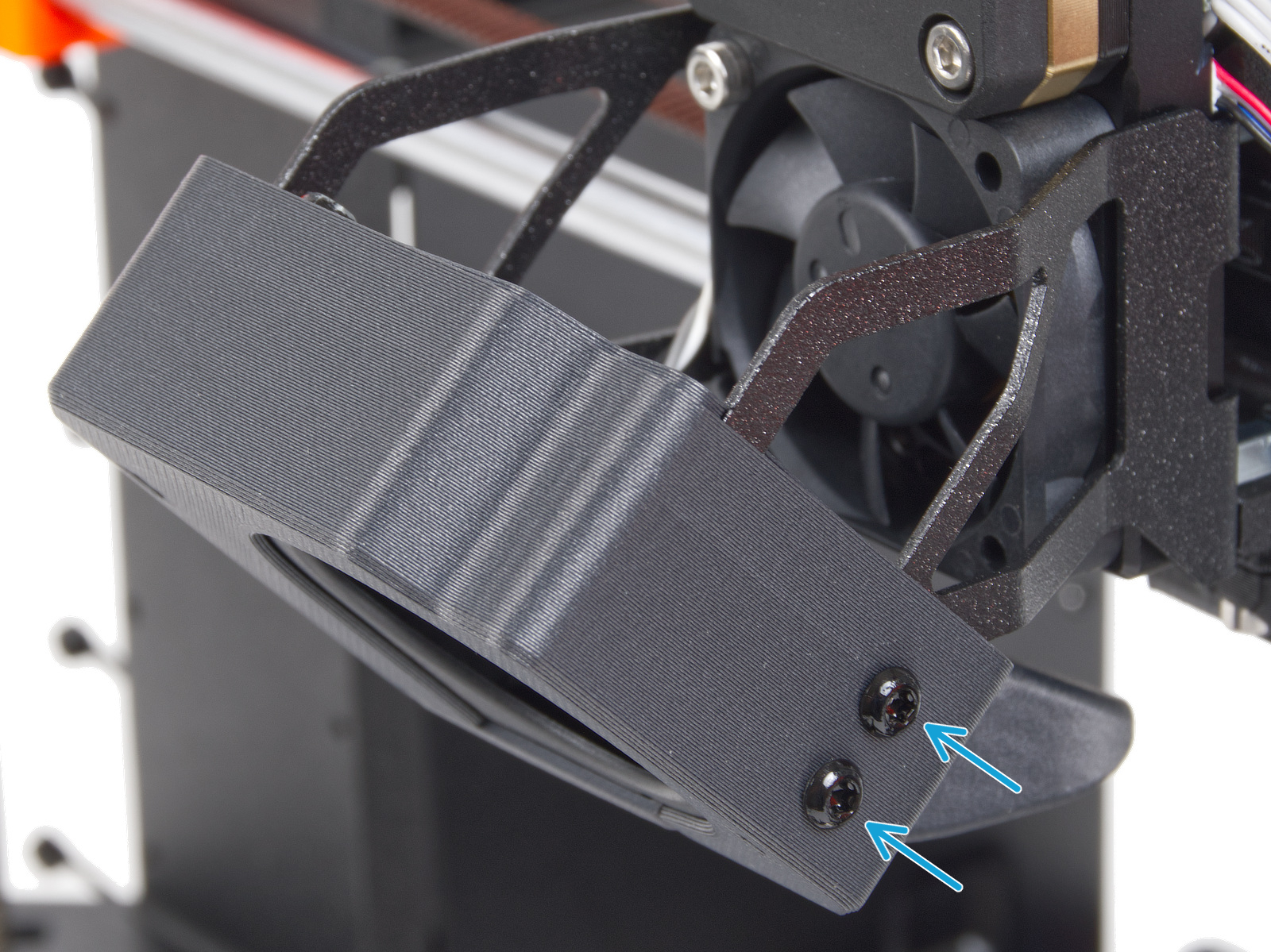 |
- Slide out the print fan assembly, and place it to the left of the hotend. Be careful to not excessively pull or pinch the attached cables.
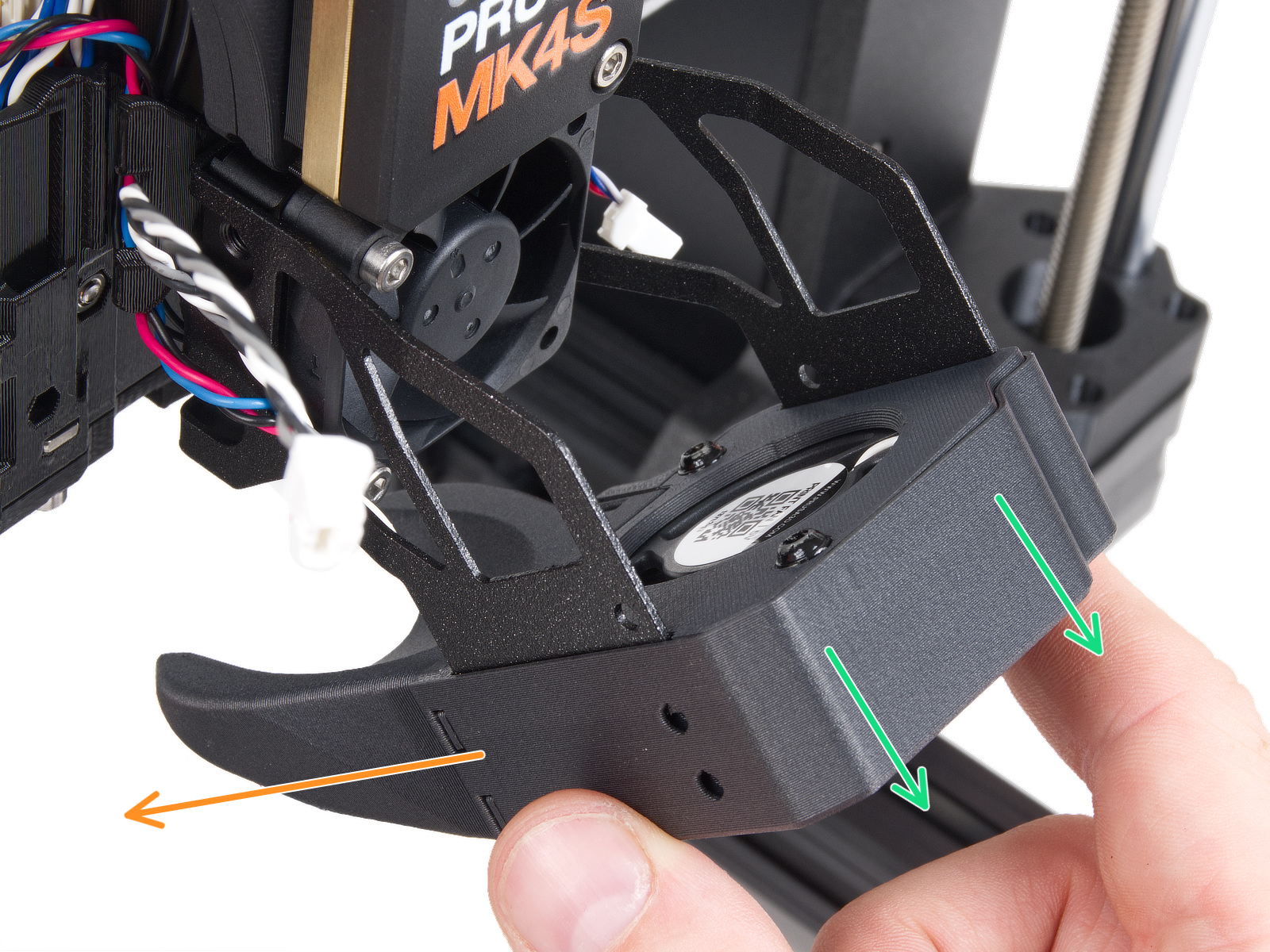
Procedure
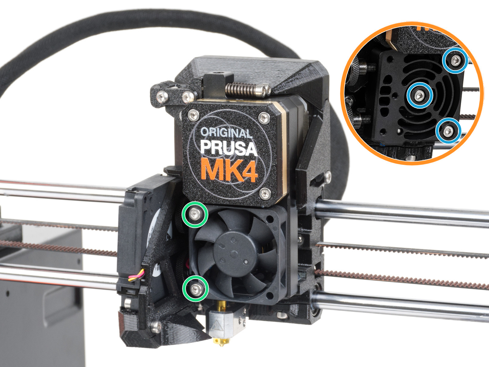
- Slightly loosen the two bolts holding the hotend fan. If this doesn't solve the issue, proceed to the next step.
- Temporarily remove the hotend fan by removing the previously adjusted bolts. This will expose the heatsink/loadcell. Then, loosen very slightly the three bolts that hold the heatsink/loadcell in place.
Loadcell white pad - visual check
PG-assembly-adapter printed with MK4/S
PG-assembly-adapter printed with MK3/S/+
- If any filament is loaded, unload the filament, then wait for the printer to fully cool down. After that, turn the printer off.
- Remove the PG-case, together with the PG-ring, gearbox, and main plate. Remove all of these parts in one piece.
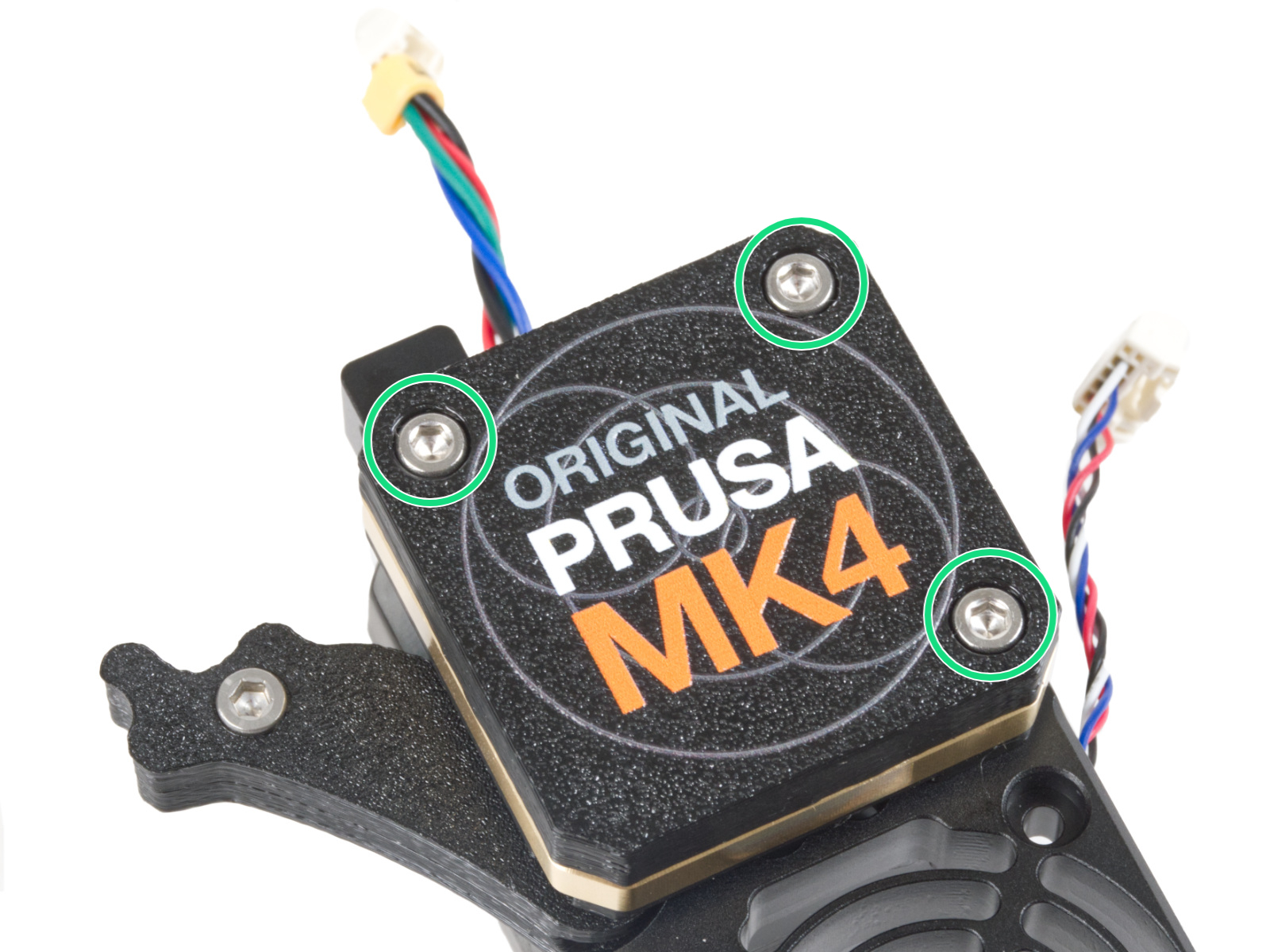 |  |
- The top part of the loadcell is now visible and has a white pad attached to it. Without touching the white pad, check it for damage.
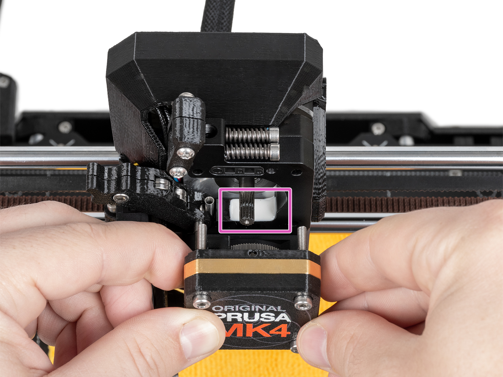
- Reassemble the block of PG-case, PG-ring, gearbox, and main plate. In case the parts are not in one block, follow the dedicated steps from the Nextruder assembly manual, depending on your printer version.
- Perform the gearbox alignment.
Commenti
Hai ancora delle domande?
Se hai una domanda su qualcosa che non è trattato qui, dai un'occhiata alle nostre risorse aggiuntive.
E se questo non dovesse funzionare, è possibile inviare una richiesta a [email protected] o tramite il pulsante qui sotto.